
Apparatus and method for automated visual distortion adjustments for a portable projection device

Inactive Publication Date: 2012-12-04
CHO SAMUEL SEUNGMIN +1
View PDF7 Cites 33 Cited by
  • Summary
  • Abstract
  • Description
  • Claims
  • Application Information

AI Technical Summary

Benefits of technology

[0010]Summary and Abstract summarize some aspects of the present invention. Simplifications or omissions may have been made to avoid obscuring the purpose of the Summary or the Abstract. These simplifications or omissions are not intended to limit the scope of the present invention.
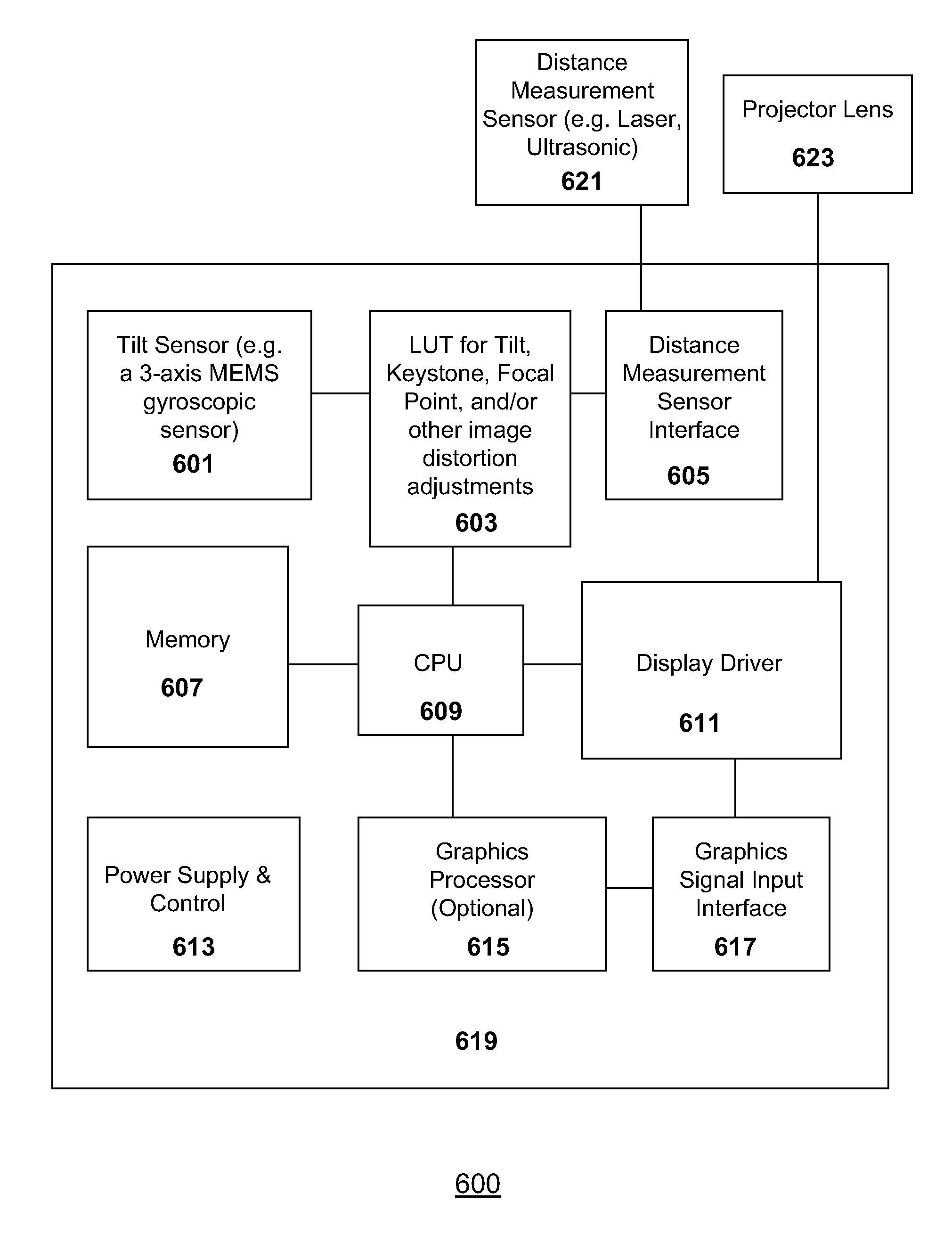
[0011]In one embodiment of the invention, an apparatus for automated visual distortion adjustments for a portable projection device is disclosed. This apparatus comprises a tilt sensor embedded in the portable projection device, wherein the tilt sensor is designed to determine a current position, a current acceleration, or a current directional orientation of the portable projection device relative to a horizontal plane or a vertical plane; a distance measurement sensor located near a projector lens embedded in the portable projection device, wherein the distance measurement sensor is designed to determine a current distance between a surface near the projector lens and a presumed projection surface; and a lookup table (LUT) unit operatively connected to the tilt sensor and the distance measurement sensor, wherein the LUT unit is designed to use sensor output values from the tilt sensor and the distance measurement sensor as a lookup table key to retrieve one or more pre-computed visual distortion adjustment values stored in the LUT unit.
[0012]Furthermore, in another embodiment of the invention, a method for automatically adjusting a visual distortion from a portable projection device is also disclosed. This method comprises the steps of: reading one or more current values from a tilt sensor to determine a magnitude of tilt, keystone distortion, or other factors for a potential visual distortion for a projector lens relative to one or more geometrical axis which define a horizontal plane or a vertical plane; reading a distance sensor for a distance measurement between a surface near the projection lens and a projected surface, wherein the projected surfa

Problems solved by technology

Once bulky and expensive in the past, projection devices are increasingly becoming miniaturized and less expensive.
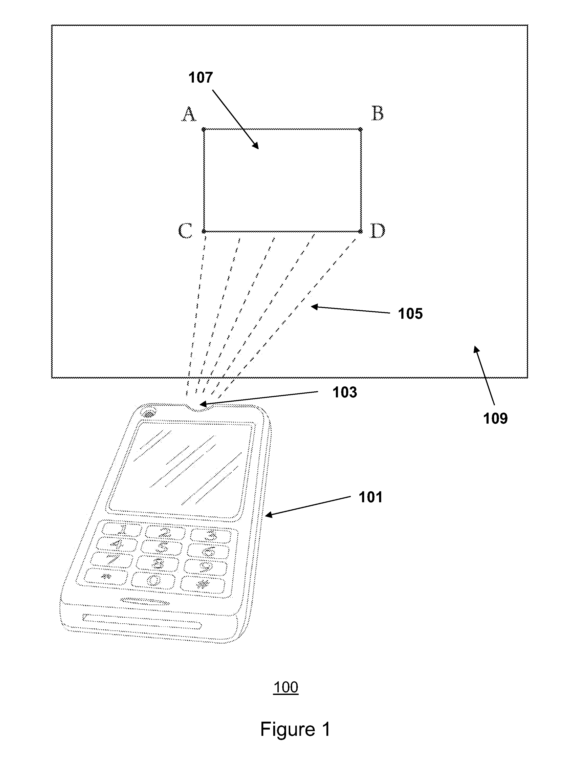
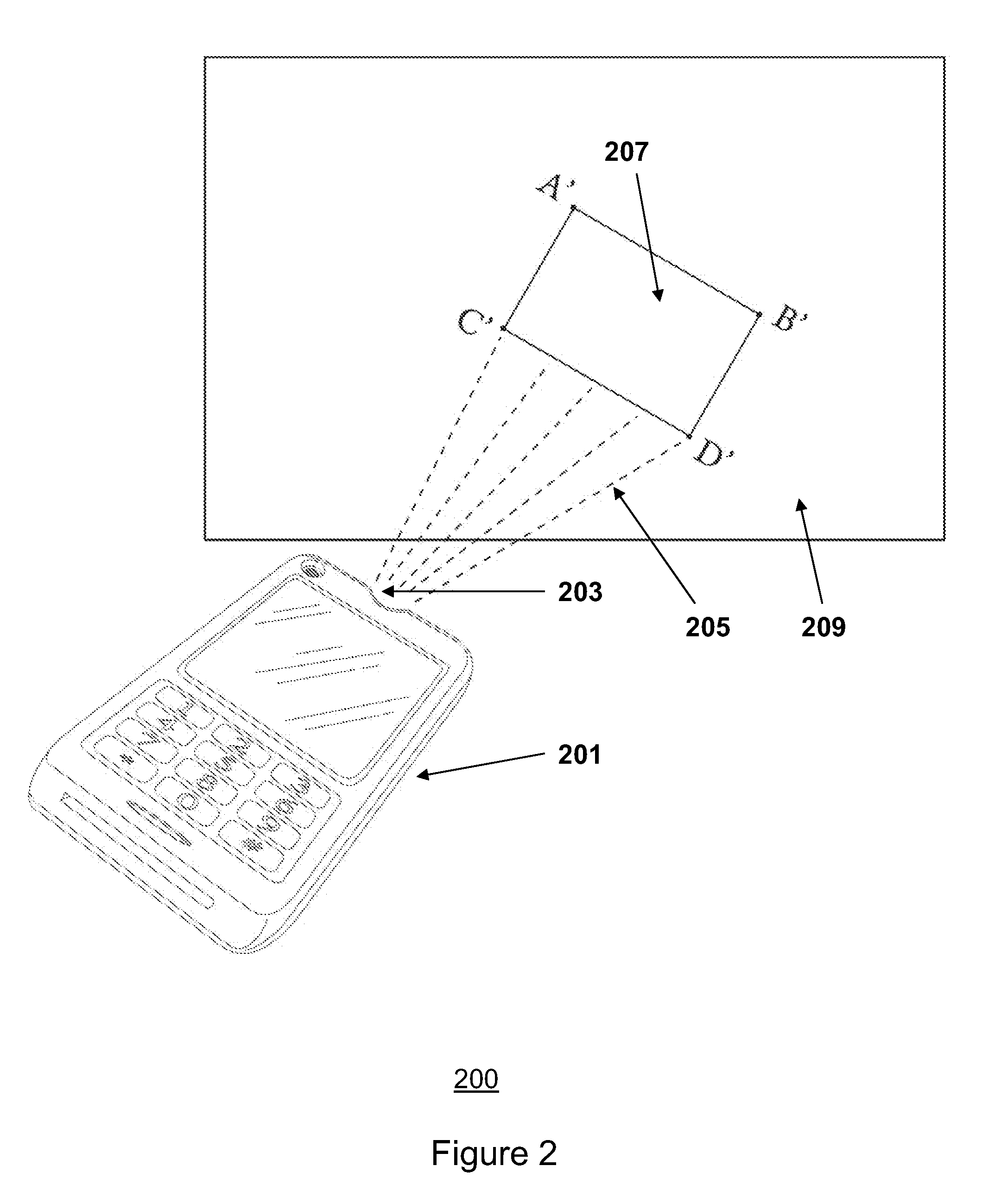
In both standalone projector devices and mobile devices with integrated projection capabilities, visual distortions introduced by non-ideal angles between a projecting medium (e.g. a projector lens) and a projected surface (e.g. a blank wall or a projection screen) can cause user inconveniences.
The computational load on a graphics processor or a microprocessor can be especially heavy, if some of the sensors used require an image capture by a camera and image interpretations for graphical transformation calculations (as in FIG. 3A and FIG. 4 of Brandon Dean Slack et al.
Heavy computational loads can result in significant processing delay, often at least several seconds from initial detection to automatic adjustments, for each image adjustment.
In practical implementations, each step of manipulating images such as image capture, captured image processing, captured image interpretations with other images, and real-time graphic transformation calculations, as disclosed in prior publications such as U.S. Ser. No. 12 / 206,554 and U.S. Ser. No. 12 / 206,546, adds a significant amount of time delay before a corrected image can be projected to a projected screen.
Any multi-second delays are unacceptable if projection image adjustments need to be made continuously in every fraction of a second at a high refresh rate.
For example, if an projection image adjustment requires fast refresh rates (e.g. 10˜20 Hz, or 10˜20 times per second for visual distortion adjustment between a projector and a projection screen), the conventional automated projected image adjustment methods such as the ones disclosed in U.S. Ser. No. 12 / 206,554 and U.S. Ser. No. 12 / 206,546 are grossly unsuitable due to a heavy processor calculation load and image capture, process, and interpretation workload.
However, these methods disclosed by Brandon Dean Slack et al. do not anticipate, suggest, or teach a method or an apparatus to enable a very rapid adjustment, or a very rapid preemptive adjustment for image projection when a projector itself is placed on a non-stationary surface, such as a user's hand which may tilt, vacillate, or move abruptly and frequently.
Because most projection devices are still envisioned and designed to be placed on a stationary flat surface, fast-refresh, real-time, and / or automated adjustments schemes to counteract tilts, rotations, keystones, or other visual distortions caused by an unstable surface (e.g. a projector on a surface of a user's hand) for a projection device are not yet available today.

Method used


Image

  • Apparatus and method for automated visual distortion adjustments for a portable projection device
  • Apparatus and method for automated visual distortion adjustments for a portable projection device
  • Apparatus and method for automated visual distortion adjustments for a portable projection device

Examples


Embodiment Construction

[0022]Specific embodiments of the invention will now be described in detail with reference to the accompanying figures. Like elements in the various figures are denoted by like reference numerals for consistency.

[0023]In the following detailed description of embodiments of the invention, numerous specific details are set forth in order to provide a more thorough understanding of the invention. However, it will be apparent to one of ordinary skill in the art that the invention may be practiced without these specific details. In other instances, well-known features have not been described in detail to avoid unnecessarily complicating the description.

[0024]The detailed description is presented largely in terms of description of shapes, configurations, and / or other symbolic representations that directly or indirectly resemble one or more apparatuses and methods for automated visual distortion adjustments for a portable projection device, wherein the portable projection device may be a s...


PUM


Abstract

An apparatus and a method are disclosed for automated projection image adjustments for a portable projection device. In one embodiment of the invention, the apparatus periodically polls a tilt sensor inside the portable projection device and uses the tilt sensor reading as a key to a lookup table which stores pre-computed visual distortion adjustment values. Furthermore, the apparatus can also poll a distance measurement sensor to measure a distance between a projector lens and a presumed projection surface periodically. The measured distance value can also be used as an additional parameter to the key for the lookup table to retrieve appropriate visual distortion adjustment values which are pre-computed and stored in the lookup table. The fast pre-computed adjustment value retrieval without real-time computation of graphical transformations to correct the visual distortions minimizes processor load, energy consumption, and processing delays for projection image corrections.

Description

BACKGROUND OF THE INVENTION[0001]The present invention generally relates to a portable projection device. More specifically, the present invention relates to an apparatus and a method for automated visual distortion adjustments for a portable projection device.[0002]Graphics and video projectors have become popular and cost effective for mass consumer markets in recent years. Once bulky and expensive in the past, projection devices are increasingly becoming miniaturized and less expensive. For example, a standalone projector in the consumer market today is gradually getting lighter, cheaper, and smaller due to projection technology advancements such as miniaturized Digital Light Processing (DLP) technologies. Furthermore, some projection devices are becoming sufficiently miniaturized to be integrated into mobile devices such as cellular phones, laptops, and dedicated portable gaming devices.[0003]Although integration of miniature projection devices into mobile devices are still earl...

Claims


Application Information

Patent Timeline
IPC IPC(8): G03B21/00
CPCH04N9/3194H04N9/3185
Inventor CHO, SAMUEL SEUNGMINKIM, CHRISTINE HANA
Owner CHO SAMUEL SEUNGMIN
Learn More