Optical fiber tracing system

Active Publication Date: 2012-12-04
TELECT
View PDF2 Cites 26 Cited by
  • Summary
  • Abstract
  • Description
  • Claims
  • Application Information

AI Technical Summary

Benefits of technology

[0011]A system for efficiently tracing one or more optical fibers within a fiber-optic communication system. The invention generally relates to a fiber-optic communication system which includes an optical fiber and a luminescent member positioned adjacent to the optical fiber. The lumin

Problems solved by technology

With this significant number of ports and pairing combinations, it can take a long time to determine which two ports in different patch panels are connected by a single optical fiber.
While fiber-optic communication systems have significant advantages over wire communication systems, it can be difficult to locate a specific optical fiber or group of optical fibers.
One problem with the conventional tracing technology is that it does not provide a means f

Method used


Image

  • Optical fiber tracing system
  • Optical fiber tracing system
  • Optical fiber tracing system

Examples


Embodiment Construction

A. Overview.

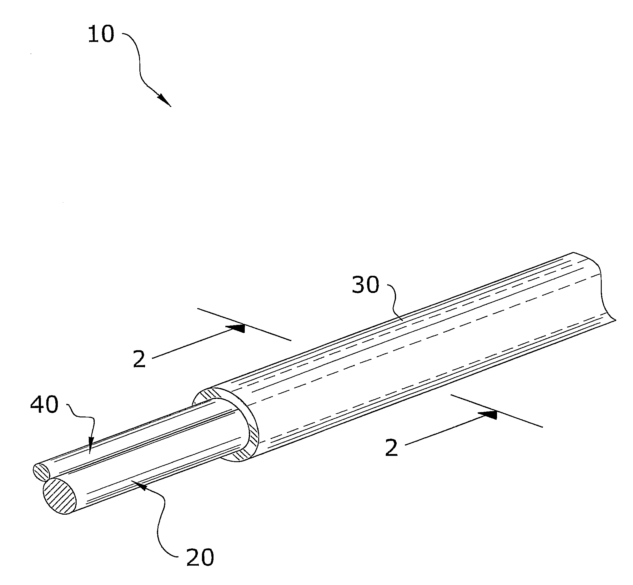
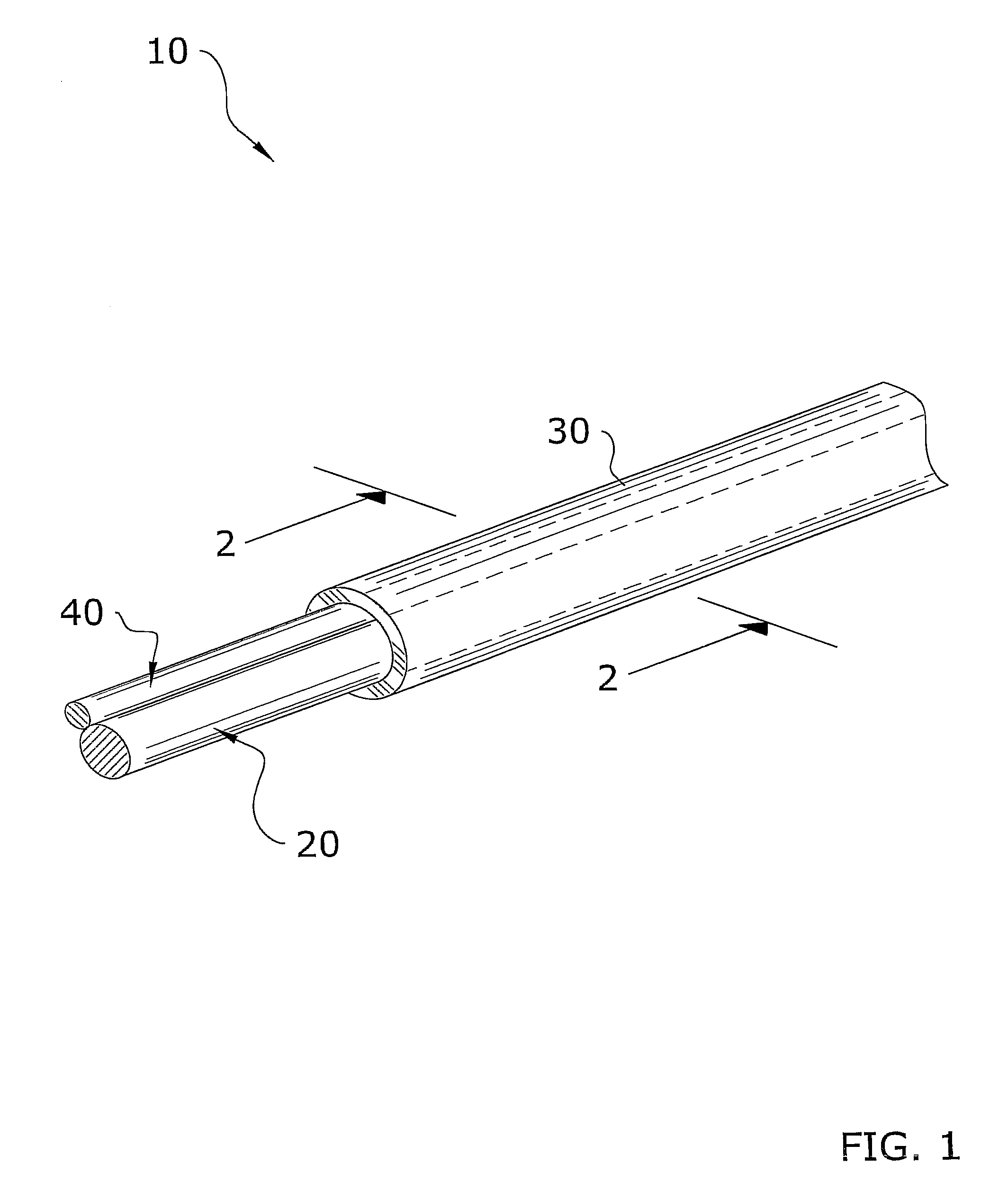
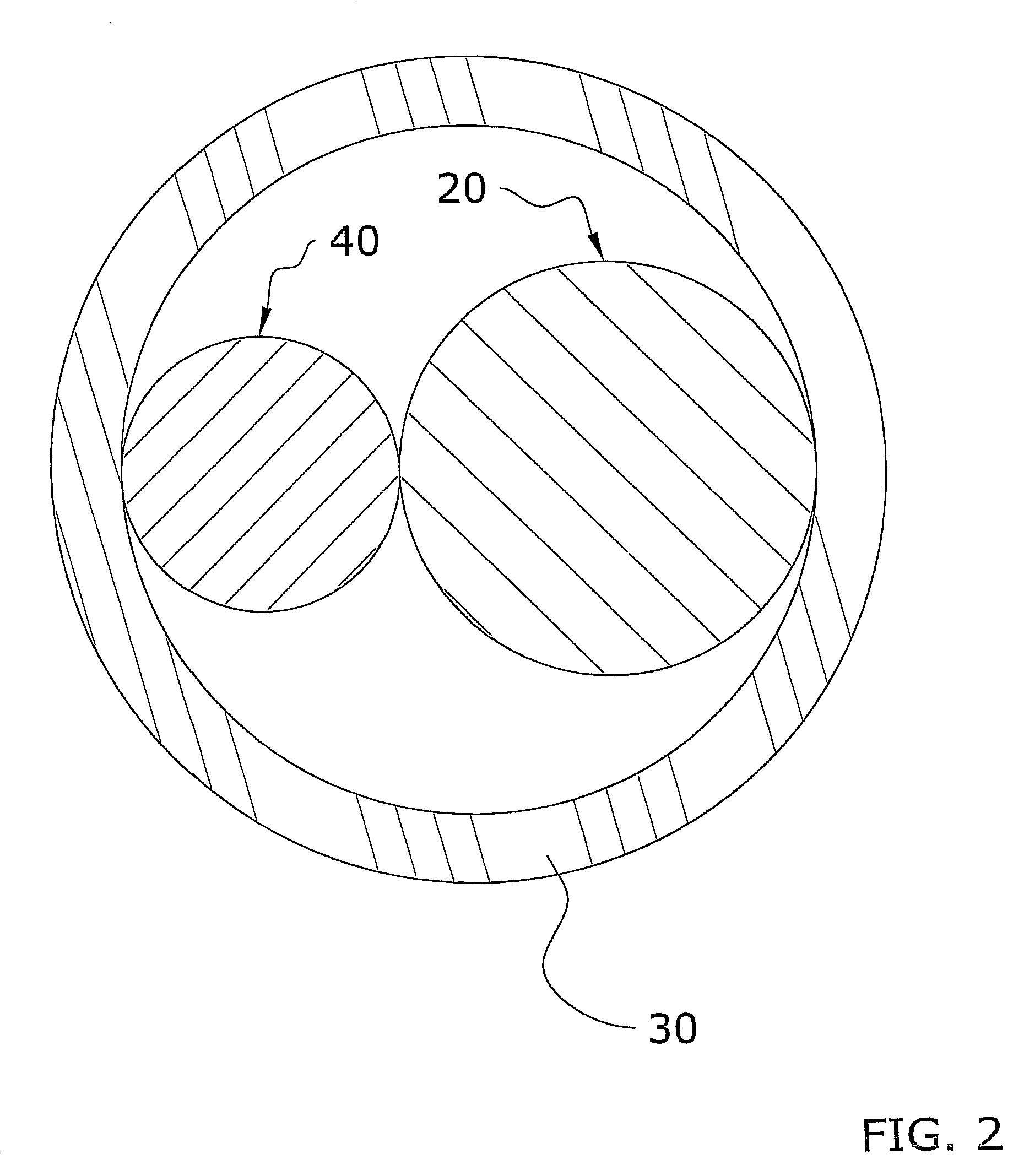
[0021]Turning now descriptively to the drawings, in which similar reference characters denote similar elements throughout the several views, FIGS. 1 through 7 illustrate an optical fiber tracing system 10, which comprises an optical fiber 20 and a luminescent member 40 positioned adjacent to the optical fiber 20. The luminescent member 40 illuminates along the length thereof for allowing a selective visual tracing of an individual optical fiber 20 or group of optical fibers 20. The luminescent member 40 is preferably comprised of an electroluminescent wire (EL wire) that extends along the length of the optical fiber 20.

B. Optical Fiber.

[0022]The optical fiber 20 is comprised of a length of material having a first end and a second end for fiber-optic communications. Conventional optical fiber 20 is comprised of a core that allows light to freely pass through, a cladding surrounding the core to reflect the light back into the core, and a protective cover to protect the cla...


PUM


Abstract

An optical fiber tracing system for efficiently tracing one or more optical fibers within a fiber-optic communication system. The optical fiber tracing system generally includes an optical fiber and a luminescent member positioned adjacent to the optical fiber. The luminescent member illuminates along the length thereof for allowing a selective visual tracing of an individual optical fiber or group of optical fibers. The luminescent member is preferably comprised of an electroluminescent wire (EL wire) that extends along the length of the optical fiber.

Description

CROSS REFERENCE TO RELATED APPLICATIONS[0001]Not applicable to this application.STATEMENT REGARDING FEDERALLY SPONSORED RESEARCH OR DEVELOPMENT[0002]Not applicable to this application.BACKGROUND OF THE INVENTION[0003]1. Field of the Invention[0004]The present invention relates generally to a fiber-optic communication systems and more specifically it relates to an optical fiber tracing system for efficiently tracing one or more optical fibers within a fiber-optic communication system.[0005]2. Description of the Related Art[0006]Any discussion of the related art throughout the specification should in no way be considered as an admission that such related art is widely known or forms part of common general knowledge in the field.[0007]Optical fibers are used in fiber-optic communication systems to transmit information over significant distances using pulses of light that pass through the optical fibers. Information transferred over a conventional fiber-optic communications system inclu...

Claims


Application Information

Patent Timeline
IPC IPC(8): F21V9/16
CPCH04Q1/136G02B6/4402G02B6/0003G02B6/4482
Inventor KNAGGS, DAVID H.DINWOODIE, CHRIS A.VANMANSUM, MICHAEL
Owner TELECT
Why Eureka
Try Eureka