Depth camera-based visual mileometer design method

A visual odometry and depth camera technology, applied in the field of computer vision technology research, can solve problems such as poor real-time performance, large amount of calculation, and limited robustness improvement

Active Publication Date: 2017-08-08
SOUTH CHINA UNIV OF TECH
View PDF3 Cites 76 Cited by
  • Summary
  • Abstract
  • Description
  • Claims
  • Application Information

AI Technical Summary

Problems solved by technology

For example: Someone proposed a visual method based on the image pixel energy function, which minimizes the sum of the squares of the pixel intensity differences of all pixels. Since it matches all pixels in the entire image, the calculation is heavy and the real-time performance is poor; or SVO directly Register the feature blocks with more prominent grayscale gradients, and then use the photometric error minimization to obtain the motion pose. Although the real-time performance of SVO is very good, it will fail to track fast and large-scale motion; others use the optical flow method and Combining the feature method, the optical flow is used to track the pose within a small displacement, and the pose is obtained by feature extraction under a large displacement, and then Kalman fusion is performed on the pose, which can improve the robustness of the odometer to a certain extent , but the robustness improvement is limited

Method used


Image

  • Depth camera-based visual mileometer design method
  • Depth camera-based visual mileometer design method
  • Depth camera-based visual mileometer design method

Examples


Embodiment Construction

[0039] The present invention will be further described in detail below in conjunction with the embodiments and the accompanying drawings, but the embodiments of the present invention are not limited thereto.

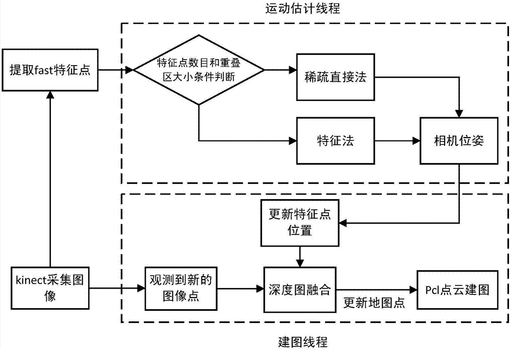
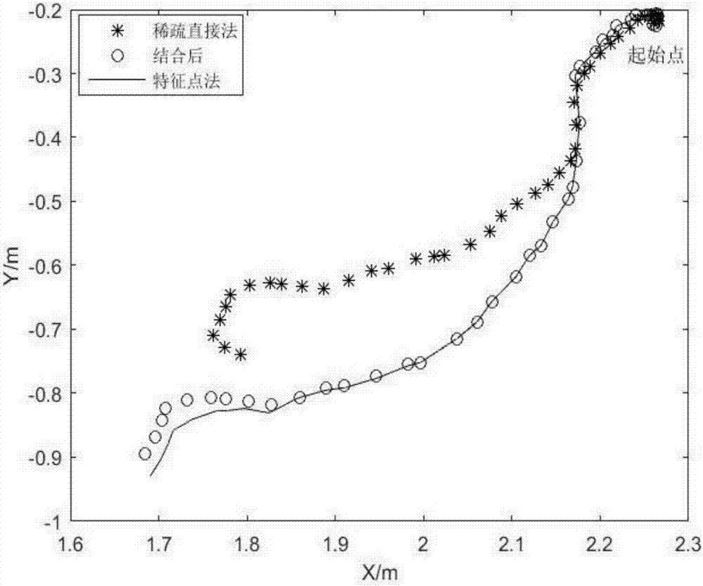
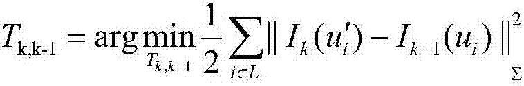
[0040] In order to solve the problem of loss of pose and poor robustness in the process of fast movement in the visual odometry based on the sparse direct method, a design method of the visual odometry based on the depth camera is proposed. This method combines the sparse direct matching method and the feature point matching method, which can improve the real-time and robustness of visual odometry.

[0041] In this method, a threshold is set for the overlapping area between two frames, and the size of the overlapping area can reflect the camera motion to a certain extent. If the overlapping area is large, the sparse direct method is used to estimate the camera pose during gentle motion, and if the overlapping area is small, the feature matching is performed and the camer...


PUM


Abstract

The invention discloses a depth camera-based visual mileometer design method. The method comprises the following steps of acquiring the color image information and the depth image information in the environment by a depth camera; extracting feature points in an initial key frame and in all the rest image frames; tracking the position of each feature point in the current frame based on the optical flow method so as to find out feature point pairs; according to the number of actual feature points and the region size of the overlapped regions of feature points in two successive frames, selectively adopting the sparse direct method or the feature point method to figure out relative positions and postures between two frames; based on the depth information of a depth image, figuring out the 3D point coordinates of the feature points of the key frame in a world coordinate system based on the combination of relative positions and postures between two frames; conducting the point cloud splicing on the key frame during another process, and constructing a map. The method combines the sparse direct method and the feature point method, so that the real-time performance and the robustness of the visual mileometer are improved.

Description

technical field [0001] The invention relates to the field of computer vision technology research, in particular to a design method of a depth camera-based visual odometer. Background technique [0002] Visual odometry is a computer vision method that uses the image sequence collected by the camera to estimate the relative motion of the agent, which plays an important role in the autonomous positioning and navigation of the robot. At present, SLAM (Simultaneous Localization and Mapping) based on vision is a hotspot in indoor positioning research, and odometry is a part of the front-end structure of SLAM. Designing a robust and fast visual odometry is very important for the entire SLAM construction. The essential. [0003] Traditional visual odometry based on feature methods (such as SIFT, ORB), etc., require a large amount of calculation for feature extraction and matching, and the entire visual odometry is time-consuming, coupled with the mismatch of feature points and the ...

Claims


Application Information

Patent Timeline
Patent Type & Authority Applications(China)
IPC IPC(8): G06T7/73G06T7/246G06T7/269G01C22/00G01C21/20
CPCG01C21/206G01C22/00G06T2207/10016G06T2207/10024G06T2207/10028
Inventor 魏武黄婷侯荣波
Owner SOUTH CHINA UNIV OF TECH
Why Eureka
Try Eureka