Solid-state light bulb

a light bulb and solid-state technology, applied in the direction of spectral modifiers, gas-filled discharge tubes, lighting support devices, etc., can solve the problems of affecting the light intensity of the beam, etc., to achieve the effect of reducing the problem

Inactive Publication Date: 2012-12-04
LIGHT PRESCRIPTIONS INNOVATORS
View PDF30 Cites 101 Cited by
  • Summary
  • Abstract
  • Description
  • Claims
  • Application Information

AI Technical Summary

Benefits of technology

[0013]The remote-phosphor approach of embodiments of the present invention reduces chip heat load as compared to conventional white LEDs, which have the phosphor directly on the chip. For example, a blue chip that radiates 35% of its electrical input as light will have a 65% heat load. A phosphor with 90% quantum efficiency and 80% Stokes efficiency will have a 10% conversion heat load and an 18% heat load from the Stokes shift for a total of 28%. Consider that 85% of the blue light goes into the phosphor and 10% comes out, so that the phosphor heat load is 28% of 75%, or 21%, of all the blue light. For currently available blue chips, the blue light output is 35% of the electrical power. This makes the phosphor heat load be 7% of the electrical power, which is much easier to dissipate by itself from the large phosphor than from the chips, which are already heat-loaded at 65% of the electrical power.
[0014]As chip technology improves, more and more of the blue light generated within the active layer is extracted from the chip. Commercial chips of today have already reached 50% efficiency (blue light output of 50% of the electrical power), and the 70-80% range is expected soon. This leaves less and less wasted energy that heats up the chip, allowing higher current levels and greater optical power output for the same heat load. In fact, once the electrodes have been sized for those higher current levels, it can be expected that the only remaining limitation upon current is whatever operating temperature is the highest tolerable. When a high-efficiency blue chip is thus operated at its peak temperature, however, a problem arises with the conventional phosphor geometry of conformal coating. When a chip is, say, 75% efficient, its heat load is only 25% but the phosphor heat load is still 21% of the blue light, which is then 16% of the electrical power. With a conformal phosphor, most of the heat from the phosphor will have to be conducted through the chip, increasing the heat load of the chip by 63% (from 25% electrical to 41% electrical). This means the heat-limited current of a conformally-coated white chip will have to be considerably lower than that of the lone blue chip.
[0016]Chip efficiencyCurrentBlue AloneCoated BluePhosphor35%350 mA53° C.56° C.67° C.80%350 mA33° C.43° C.68° C.80%1340 mA 60° C.89° C.180° C. The bottom row of the table shows a 29° C. elevation of the operating temperature of a high-amperage blue-chip with a conformal coating compared to one without any phosphor. This temperature elevation would only grow with more amperage, reaching the temperature ceiling of the chip, usually 125° C., much sooner than for the lone blue chip used in embodiments of the present invention. However, in the bottom row of the table the phosphor layer in the conformal coated packaged LED already reaches a temperature of 180° C. Such a high phosphor temperature will significantly reduce the quantum efficiency of the phosphor, adding yet more to the heat load.
[0017]Thus one of the advantages of embodiments of the present invention is that they can provide a remote phosphor geometry that prevents these over-temperature problems from arising at all, or substantially mitigates the problems. A further advantage of embodiments of the present invention is that they can operate just as well with a single blue chip as with many blue chips. Once high-efficiency chips have proven out for, say, 3 Amperes, only one chip will be necessary here. The same design can handle one or more chips. Thus, an optical design developed for several presently available chips can easily be adapted to use fewer or a single chip as and when more powerful chips become available. As was previously mentioned, in embodiments of the invention the chips only need to be located on or near the phosphor ball on a slope that is nearly the same as the tangent on its bottom perimeter.

Problems solved by technology

That configuration, however, tends to have cooling problems because of the restricted size of the thermal pathway relative to the energy density on the surface of the spherical ball.
Secondly, there are dark zones because the LED sources cannot be mounted so as to fully populate a sphere, using square die or existing packaged LEDs.
However, that arrangement results in a beam with visibly different color temperatures in different directions, something found unaesthetic.
Also, placement of the chips onto a spherical shape is difficult, and does not lend itself to volume production techniques that typically use pick and place machines.

Method used


Image

  • Solid-state light bulb
  • Solid-state light bulb
  • Solid-state light bulb

Examples


Embodiment Construction

[0045]A better understanding of various features and advantages of the present invention may be obtained by reference to the following detailed description and accompanying drawings, which set forth illustrative embodiments in which certain principles of the invention are utilized.

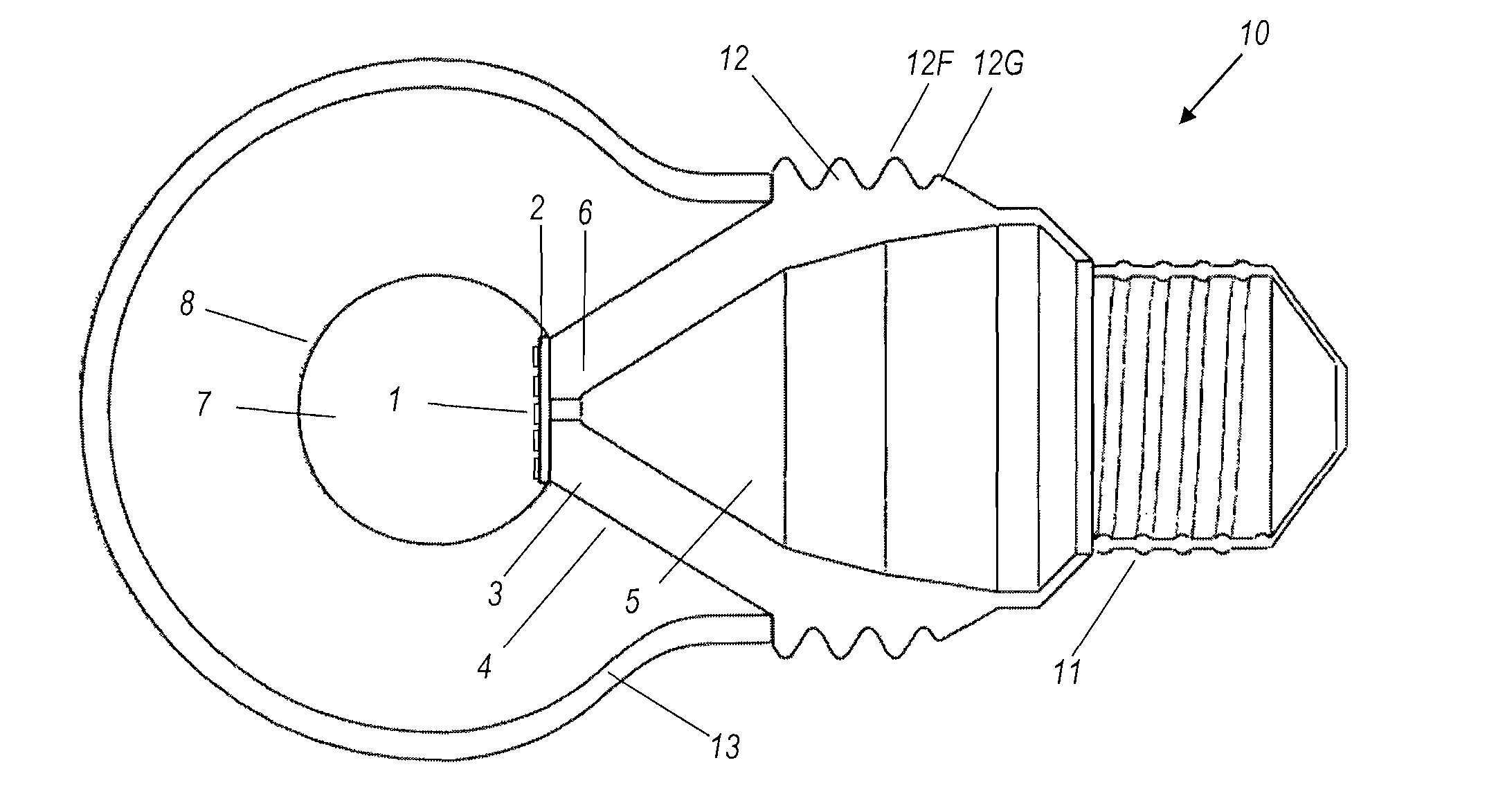
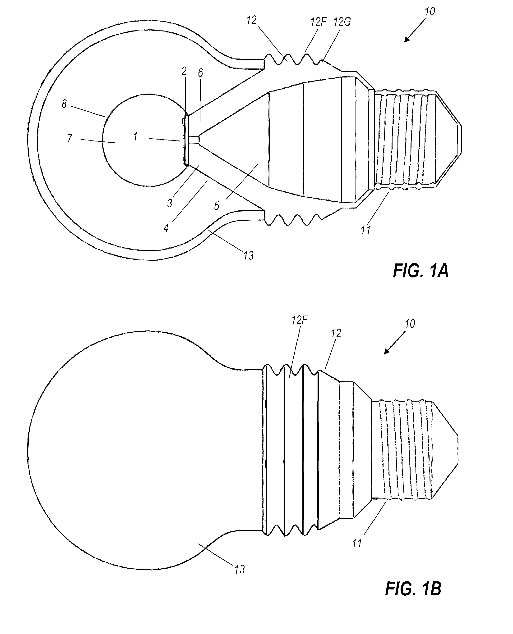
[0046]Referring to the drawings, and initially to FIGS. 1A and 1B (collectively FIG. 1), one embodiment of an LED light bulb 10 comprises an array 1 of blue LED chips mounted upon circuit board 2. Circuit board 2 is in turn mounted upon thermally conducting frame 3. The front part of conductive frame 3 is a cone frustum, with the circuit board 2 mounted on the flat top of the frustum. The conical exterior surface 4 of the conical part of conducting frame 3 is diffusely reflective (white). Frame 3 encloses an interior space 5 that contains power and control circuitry (not shown in detail) for the LED light engine (i.e., LED array 1 and circuit board 2). A transparent ball 7 is optically coupled to LED array...


PUM


Abstract

An example of this light bulb has a light emitting element (which may be an LED array) mounted on a circuit board. The circuit board is mounted on one end of a heat-conducting frame. An Edison screw or other suitable connector, for attaching the light bulb electrically and mechanically to a receptacle, is mounted on the other end of the frame. A transparent phosphor-coated ball has a flat chord face optically bonded to said array. A light-permeable globular enclosure is mounted on the frame, surrounding the ball and both homogenizing the white light output of the bulb but also concealing the yellowing unlit appearance of the remote phosphor ball centrally located within it.

Description

CROSS REFERENCE TO RELATED APPLICATIONS[0001]This application claims benefit of: U.S. Provisional Application 61 / 279,586 filed Oct. 22, 2009 titled “Lamp” by several of the inventors; U.S. Provisional Patent Application 61 / 280,856, filed Nov. 10, 2009, U.S. Provisional Patent Application 61 / 299,601, filed Jan. 29, 2010, and U.S. Provisional Patent Application 61 / 333,929 filed May 12, 2010, all titled “Solid-State Light Bulb With Interior Volume for Electronics,” all by some of the same inventors; and U.S. Provisional Application 61 / 264,328 filed Nov. 25, 2009 titled “On-Window Solar-Cell Heat-Spreader” by several of the inventors. All of those applications are incorporated herein by reference in their entirety.[0002]Reference is made to co-pending and commonly owned U.S. patent application Ser. No. 12 / 378,666 (publication no. 2009 / 0225529) titled “Spherically Emitting Remote Phosphor” by Falicoff et al., Ser. No. 12 / 210,096 (publication no. 2009 / 0067179) titled “Optical Device For L...

Claims


Application Information

Patent Timeline
Patent Type & Authority Patents(United States)
IPC IPC(8): F21S13/10F21V9/40
CPCF21K9/135F21V29/75F21V3/0481F21K9/56F21Y2101/02F21Y2113/005F21K9/232F21K9/64F21Y2113/13F21Y2115/10F21V3/12
Inventor FALICOFF, WAQIDISUN, YUPIN
Owner LIGHT PRESCRIPTIONS INNOVATORS
Why Eureka
Try Eureka