Binder

a technology of binding and ring, which is applied in the field of binding, can solve the problems of difficult to hold the narrow back part and maintain the binding, the ring parts might not be inserted into the punched holes formed in papers, and the inclination of the binding orientation is prevented

Active Publication Date: 2012-12-04
MAX CO LTD
View PDF10 Cites 1 Cited by
  • Summary
  • Abstract
  • Description
  • Claims
  • Application Information

AI Technical Summary

Benefits of technology

[0016]According to one or one or more embodiments of the invention, A binder is configured such that a plane portion is formed on an outer peripheral surface of at least one ring part at a portion intersecting with a back part of the binder, and such that, when a binder holding member of a binding processing machine holds the binder, the plane portion of the binder contacts with a plane table provided on the binder holding member. Therefore, the binder is held in such a state that the binder cannot incline or rotate. Thus, a binding processing operation can be carried out in the binding processing machine while the binder is held in a regular orientation. Accordingly, a mounting failure due to an inclined orientation of the binder and be resolved.
[0017]According to one or one or more embodiments of the invention, also when the back part includes a step portion and the step portion can be held by the binder holding member of the binding processing machine, the inclination of the orientation of the binder can be prevented. Combined use of the ring parts including the plane portions and the back part including the step portion can further prevent the inclined orientation of the binder.

Problems solved by technology

Thus, it is difficult to use this binder in a binding processing machine which does not require the manual operation.
However, it is not easy to hold the narrow back part and maintain the binder in a proper orientation until the binding processing is completed.
When the binder is rotated about the back part thereof and is thereby inclined from its regular orientation, the ring parts might not be inserted into punched holes formed in papers or the ring parts might not be fitted with each other properly.

Method used


Image

  • Binder
  • Binder
  • Binder

Examples


embodiment 1

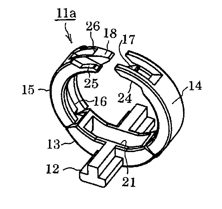
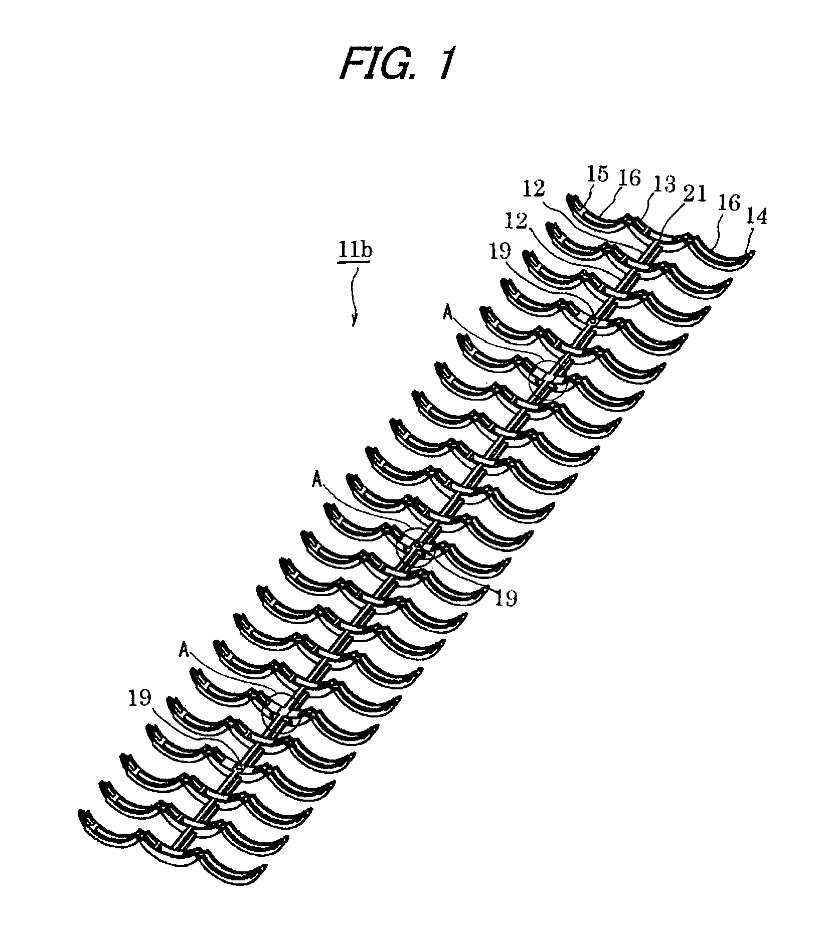
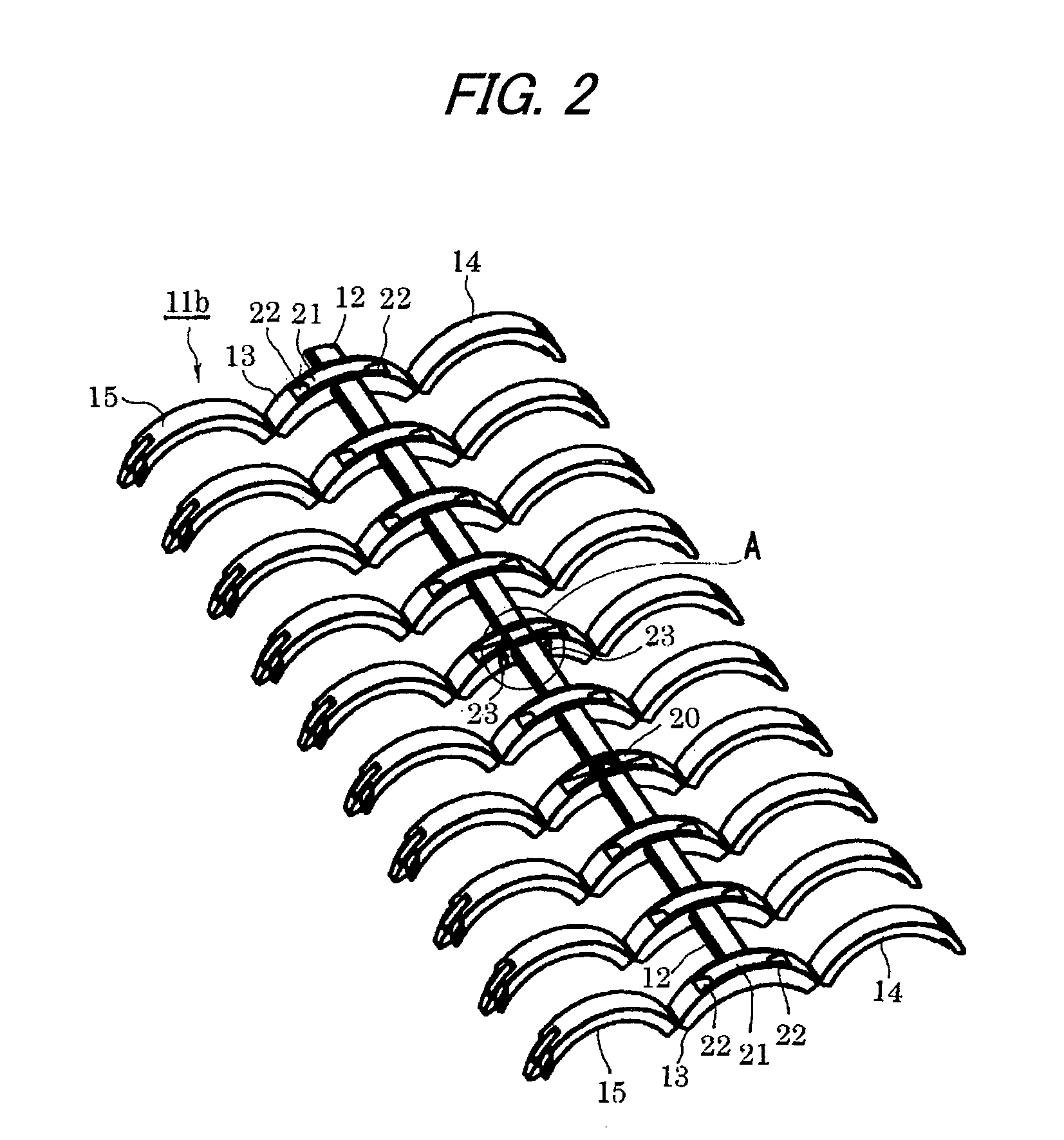
[0071]FIGS. 1 to 4(b) respectively show a binder lib. The binder lib is a plastic injection molded product which includes a back part 12 having a T-shaped section and ring parts 13, 14 and 15 connected to each other at given intervals by the back part 12. The ring part is sectioned into three parts, namely, a center ⅓ ring part 13 connected to the back part 12, and two ⅓ ring parts 14 and 15 respectively connected to the two ends of the center ⅓ part 13 through their respective small-thickness hinge portions.

[0072]As shown in FIGS. 1 and 3(b), grooves 16 are formed on the inner peripheral surfaces of the ⅓ ring parts 14 and 15 so as to extend in the circumferential direction of the ring part. A hook portion 17 is formed on the leading end of one ⅓ ring part 14, and a catch portion 18, with which the hook portion 17 can be fitted, is formed on the leading end of the other ⅓ ring part 15. In operation, the paired ⅓ ring parts 14 and 15 are rotated about the hinge portions, and their r...


PUM

PropertyMeasurementUnit
structureaaaaaaaaaa
smoothnessaaaaaaaaaa
diameteraaaaaaaaaa

Abstract

A binder is configured such that a plane portion is formed on an outer peripheral surface of at least one ring part at a portion intersecting with a back part of the binder, and such that, when a binder holding member of a binding processing machine holds the binder, the plane portion of the binder contacts with a plane table provided on the binder holding member. Because the binder contacts the plane table on the binder holding member when the binder holding member holds the binder, the binder is held in such a state that the binder cannot incline or rotate. Thus, a binding processing operation can be carried out in the binding processing machine while the binder is held in a regular orientation. Accordingly, a mounting failure due to an inclined orientation of the binder and be resolved.

Description

TECHNICAL FIELD[0001]The present invention relates to a binder for binding brochures such as documents.BACKGROUND ART[0002]JP 2000-289376 A discloses a plastic-made binder which is used to bind loose-leaf papers on the market or documents punched by a multi-hole puncher. This binder is a one-piece molded product in which a large number of ½ ring portions are arranged at given intervals in two lines on both sides of a back part of the binder, and the back part of the binder itself is a hinge composed of two divided sections. With the back part between the two lines, one line of ½ ring portions respectively include spherical-shaped projections on the leading ends thereof, whereas the other line of ½ ring portions respectively include in the leading ends thereof holes respectively having shapes corresponding to their associated projections. When the spherical-shaped projections and holes are fitted with each other, the two lines of paired ½ ring portions are connected together, thereby...

Claims


Application Information

Patent Timeline
Patent Type & Authority Patents(United States)
IPC IPC(8): B42F13/20
CPCB42B5/08B42F13/22
Inventor IGATA, KAZUYASHIMAMURA, MASASHI
Owner MAX CO LTD
Why Eureka
Try Eureka