Mooring pendant apparatus

a technology of pendant and mooring rod, which is applied in the direction of load-engaging elements, vessel construction, fastening means, etc., can solve the problems of unassisted boaters finding it impossible to moor their boats, difficulty created in trying to tie the rope to the buoy ring may be just as hard, and the boater may even find it impossible to moor his boat. , to achieve the effect of creating leverage for the retractor lever, safe and convenien

Inactive Publication Date: 2012-12-11
CARDARELLI VENANZIO +1
View PDF17 Cites 11 Cited by
  • Summary
  • Abstract
  • Description
  • Claims
  • Application Information

AI Technical Summary

Benefits of technology

[0005]The present invention overcomes the problems outlined above and provides a safe and convenient clip for docking a boat to a mooring structure with the aid of a mooring pendant apparatus. The apparatus releasably couples or decouples to an eyelet on the bow of the boat or to a buoy. The apparatus includes a clip that may open and close for attachment or release. The clip comprises an integral hook and ring which define a mouth therebetween. The hook section includes an attachment hook which accommodates a movable arm having an upper bridge section, which is biasly forced into the attachmet hook by an internal spring located in the movable arm and therein exerts a tension on the bridge section to keep the clip in a closed position. The ring section includes an access of rotation hole which provides an anchoring position for a functional retractor lever, which includes a pair of right and left lower and upper arm sections, the lower and upper arms forming a variable angular deviation in relationship to each other while maintaining the arms in a bowed position. The retractor lever also has a curved contact section that is in functional engagement with the movable arm, and a leg section extending downwardly and which has an extension piece located at a distal end that frictionally fits with great bias into the access of rotation hole of the ring section to create leverage for the retractor lever. A central rod has a first end connected to the ring section of the clip and an opposing end containing a displaced eyelet, which has an opening for connection to a mooring rope. A cable is attached to the retractor lever for activation of the apparatus. The cable passes through a cable guide and then is secured to movable handle and is then secured to a fixed handle wherein a boater may pull on the movable handle with sufficient force to overcome the locking tension placed by the internal spring on the movable arm, therein opening the clip, which may then be closed by releasing the pull on the cable.

Problems solved by technology

Because of the difficulty in securing a mooring rope to a relatively remote eye member, such as one found on the bow of a boat, the boater often neglects this procedure and only ties the boat to the cleats on the top surface of the boat.
The difficulty created in trying to tie the rope to the buoy ring may be just as hard because the boater must reach down for the buoy and then often must pull it up to tie the line.
The problem encountered in trying to tie a mooring rope to the ring on the bow of a boat is usually due to the awkward position in which most bow rings are located.
Reaching over and trying to reach the bow ring may be very hazardous to a boater, especially in rough waters.
An unassisted boater may even find it impossible to moor his boat.
It may be especially difficult to attach and detach a tie line to a mooring buoy or a boat bow ring or eyelet, in situations where a boat is not small enough to permit the user to reach down and manually fasten or unfasten the clip.
Also, tying the mooring line to cleats on the deck of the boat creates chafe which can weaken and eventually cause failure of the mooring line.
And, with more boats being built with pop-up or pull-up cleats there is the problem of failure from the constant stress of the mooring line.
Such assemblies are often difficult to use.

Method used


Image

  • Mooring pendant apparatus
  • Mooring pendant apparatus
  • Mooring pendant apparatus

Examples


Embodiment Construction

[0020]Preferred embodiments of the invention will now be described with reference to the Figures. Some terms used in the description and the appended claims are defined below.

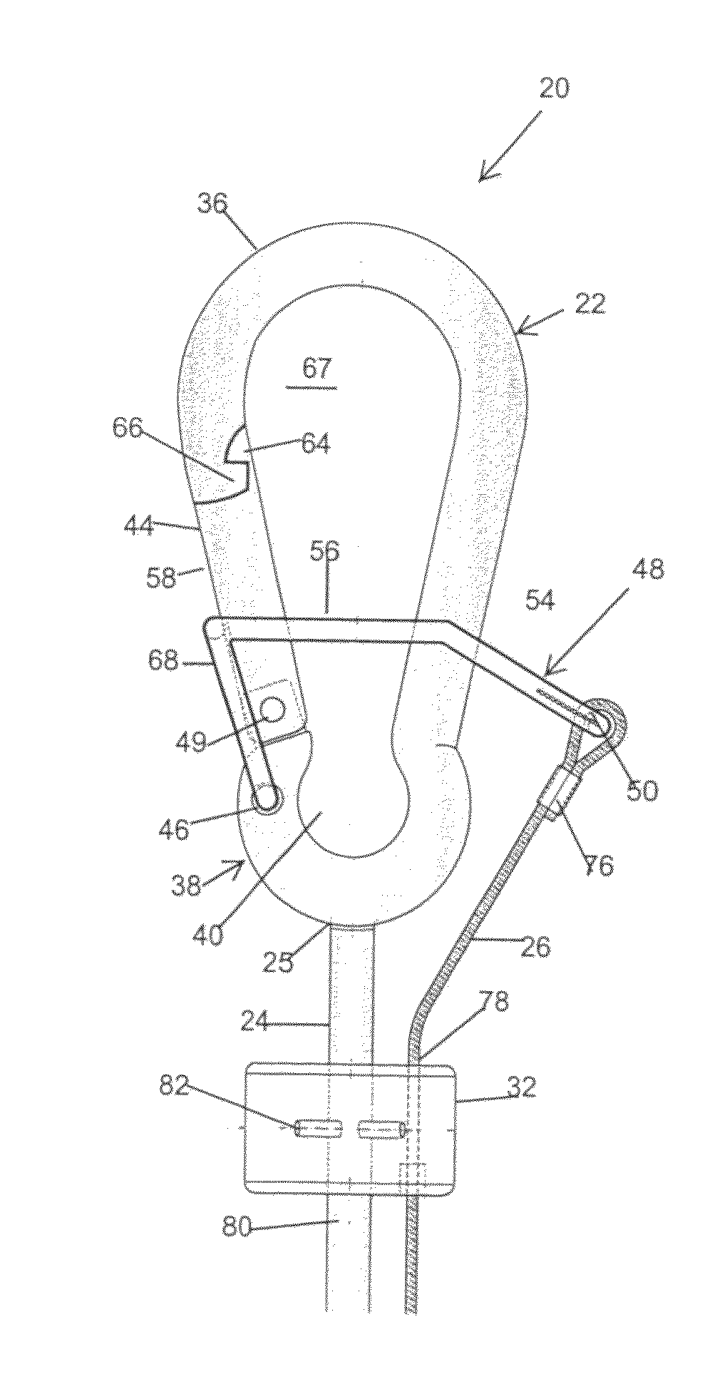
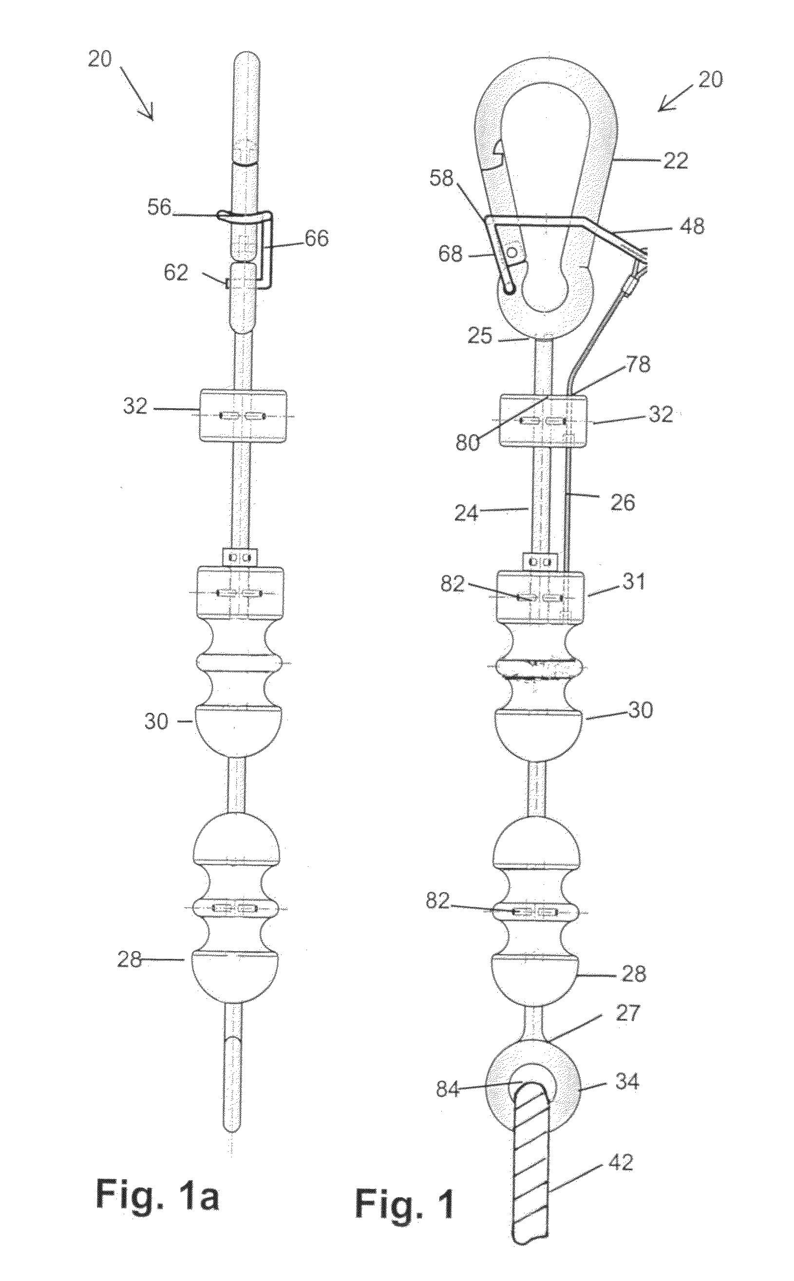
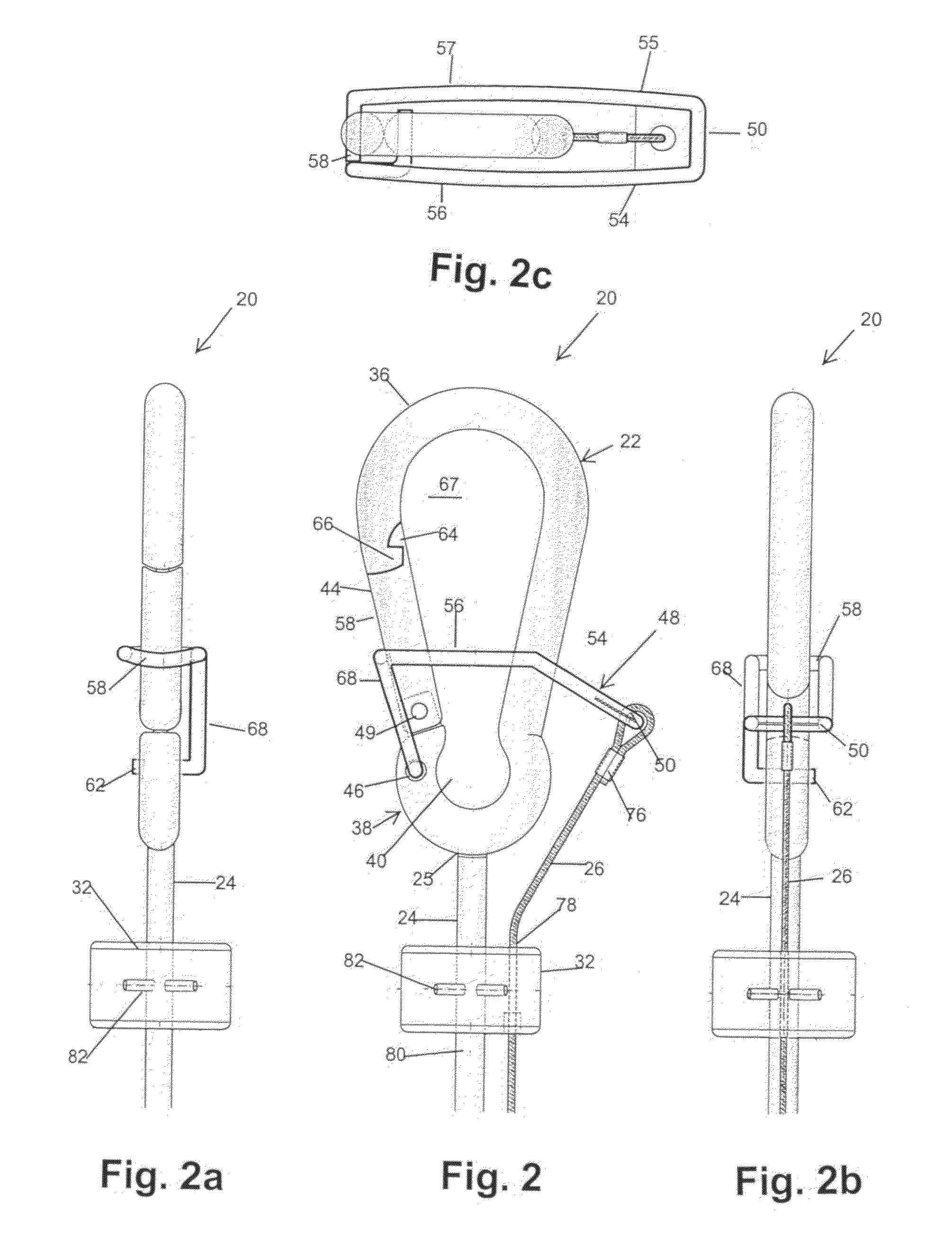
[0021]Referring to FIG. 1, the illustrated mooring pendant apparatus 20 is comprised of the following portions: a clip 22; a central rod 24; a cable 26 that when pulled or released controls the clip 22; handles, both a fixed handle 28, and a movable handle 30; a cable guide 32; and a displaced eyelet 34. The pendant apparatus 20 facilitates the placement and removal of the clip 22 from a boat ring (not shown) or a mooring ball (not shown). The clip 22 connects to the boat ring and / or to a mooring ball through the medium of a mooring line 42 (typically a rope) for the proper securing of the watercraft while in the water. The boater may opt to keep the apparatus onboard and connect to the mooring line, depending on the connectivity design chosen for that particular mooring line. The present apparatus 20 aids the ...


PUM


Abstract

A mooring pendant apparatus for releasably coupling and decoupling a boat. The apparatus having a clip comprising hook and ring sections, with an opening therebetween defining a mouth. A spring loaded movable arm tension biased such that the mouth is kept closed, and it only opens upon activation by a boater pulling on a cable. A functional retractor arm for exerting a greater force on the movable arm than exerted by the internal spring such that the clip opens upon the boater pulling on a cable line. The mooring pendant apparatus operates as an extension of the boater's arm, and it can be utilized either by keeping the apparatus on the boat or leaving it connected to the mooring line and also to the mooring ball.

Description

CROSS-REFERENCE TO RELATED APPLICATIONS[0001]This application is a continuation-in-part of co-pending U.S. patent application Ser. No. 13 / 199,248 filed Aug. 24, 2011, the disclosure of which is incorporated by reference herein in its entirety.FIELD OF THE INVENTION[0002]This invention relates to an apparatus for releasably coupling and decoupling a clip to facilitate mooring a boat. More specifically, the apparatus allows for easier attachment of a mooring line to the bow of a boat.BACKGROUND OF THE INVENTION[0003]Pleasure boats, such as yachts and small boats, are often moored to either a dock cleat or a mooring buoy. The mooring line is tied around the dock cleat or through a mooring ring on a buoy. Preferably the mooring line is tied to a ring or eye member that is found on the bow of the boat. Because of the difficulty in securing a mooring rope to a relatively remote eye member, such as one found on the bow of a boat, the boater often neglects this procedure and only ties the b...

Claims


Application Information

Patent Timeline
Patent Type & Authority Patents(United States)
IPC IPC(8): B66C1/36
CPCB63B21/54F16B45/025F16B45/021
Inventor CARDARELLI, VENANZIOWOLF, RONALD A.
Owner CARDARELLI VENANZIO
Why Eureka
Try Eureka