
Multi-way selector valve

a selector valve and multi-way technology, applied in the direction of valve operating means/releasing devices, mechanical equipment, transportation and packaging, etc., can solve the problems of device unduly stopping, high pressure refrigerant rise, device pressure rise, etc., to suppress any excessive rise in pressure

Active Publication Date: 2012-12-11
FUJIKOKI CORP
View PDF9 Cites 6 Cited by
  • Summary
  • Abstract
  • Description
  • Claims
  • Application Information

AI Technical Summary

Benefits of technology

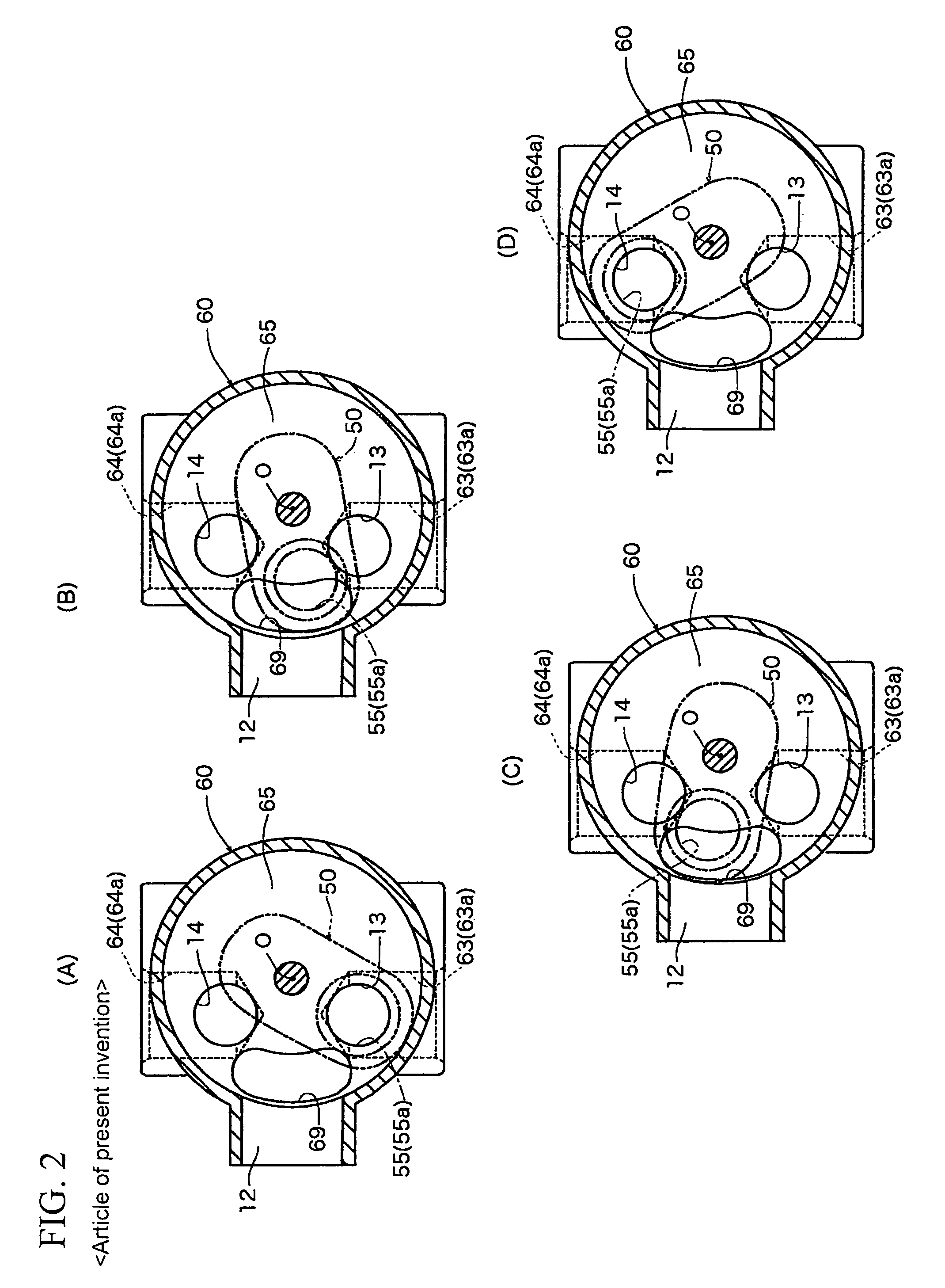
The present invention is a multi-way selector valve that prevents excessive rise in pressure of high-pressure refrigerant during the transitional phase of flow path switching, which can cause malfunctioning of the flow path switching operation and erroneous judgments of anomaly / failure occurrences in the device. The valve has an escape passage portion that allows the high-pressure refrigerant to escape to the valve chest, resulting in a decrease in pressure. This prevents malfunctioning of the flow path switching operation and prevents erroneous judgments of fail-safe mechanisms.

Problems solved by technology

When the outlet side of the high-pressure passage portion 55 is thus closed during the transitional phase in flow path switching, the high-pressure refrigerant on the compressor discharge side is left with no escape, albeit for a very short time, and the pressure, of the high-pressure refrigerant rises sharply, thereby possibly giving rise to such problems as malfunctioning of the flow path switching operation, erroneous judgments of anomaly / failure occurrences in the device by a fail-safe mechanism causing the device to stop unduly, and the like.

Method used


Image

  • Multi-way selector valve
  • Multi-way selector valve
  • Multi-way selector valve

Examples


Embodiment Construction

[0047]Embodiments of four-way selector valves according to the present invention are described below with reference to the drawings.

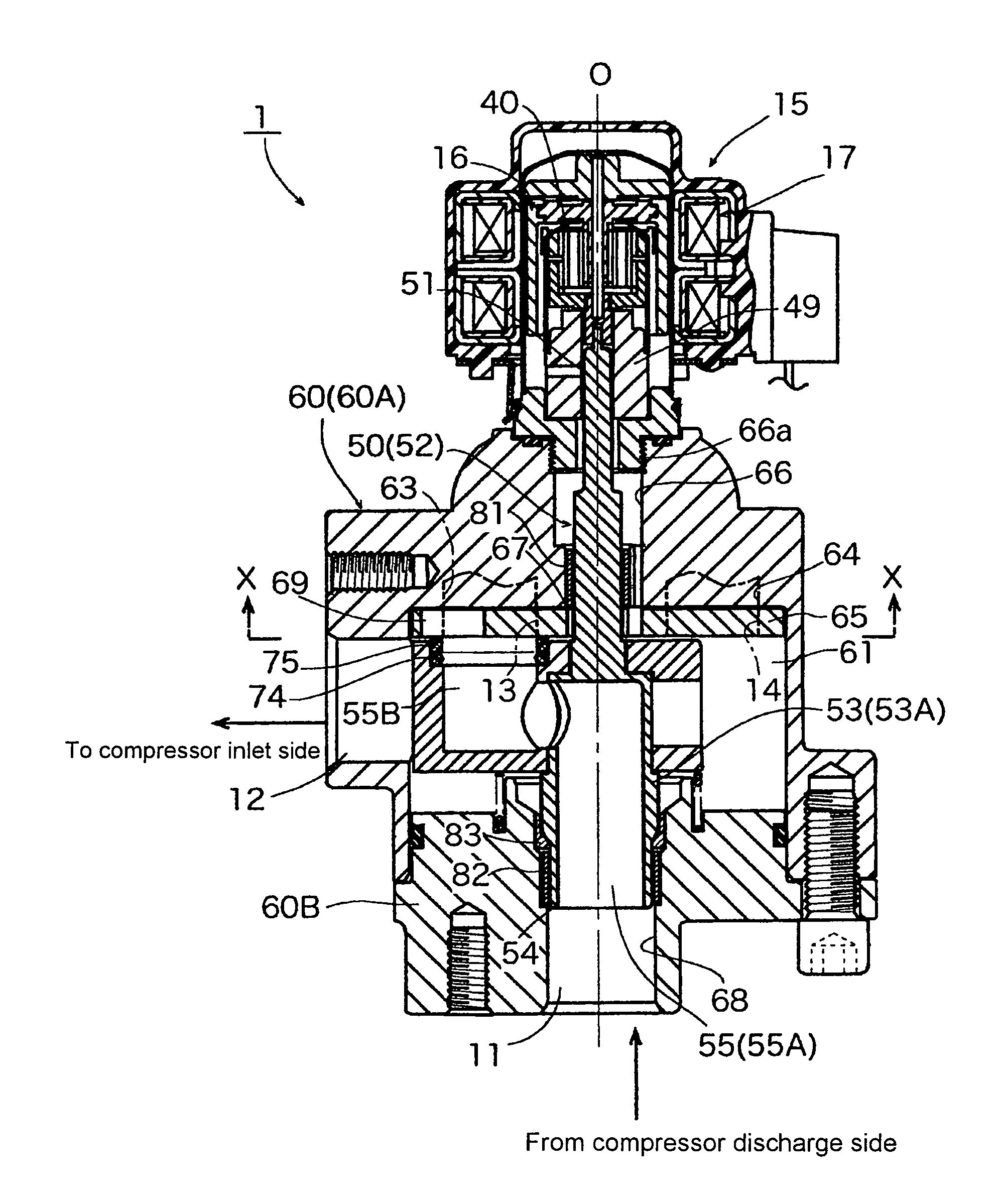
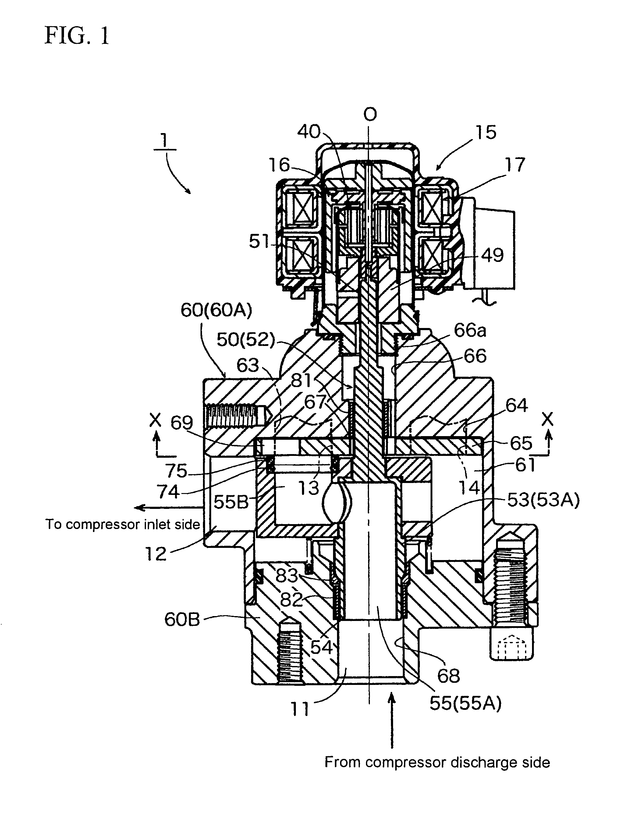
[0048]FIG. 1 is a vertical sectional view showing an embodiment of a multi-way (four-way) selector valve according to the present invention. With respect to a four-way selector valve 1 of the present embodiment, like parts to those of the previously discussed conventional four-way selector valve 1′ shown in FIG. 3 are denoted with like reference numerals.

[0049]The four-way selector valve 1 in the illustrated example is also used in refrigeration cycles of car air-conditioners and the like, and comprises: a valve member 50 that is rotated by a motor 15 as an actuator comprising a rotor 16 and a stator 17; and a valve body 60 that rotatably holds this valve member 50.

[0050]In the four-way selector valve 1 of the present embodiment, an epicyclic gear decelerating mechanism 40 is mounted between the rotor 16 of the motor 15 and the valve member 50, and the ...


PUM


Abstract

There is provided a multi-way selector valve capable of suppressing any excessive rise in the pressure of a high-pressure refrigerant during a transitional phase of flow path switching and of preventing malfunctioning of a flow path switching operation, while also being capable of preventing situations in which erroneous judgments of anomaly / failure occurrences in the device are made by a fail-safe mechanism to cause the device to stop unduly. A high-pressure passage portion 55 to which a high-pressure fluid is introduced is formed in a valve member 50. A valve seat portion 65 provided with a first inlet / outlet 13 and a second inlet / outlet 14 that are selectively communicated with an outlet-side end portion 55a of the high-pressure passage portion 55, and a valve chest 61 into which a low-pressure fluid is selectively introduced via the first inlet / outlet 13 and the second inlet / outlet 14 are provided in a valve body 60. During the transitional phase of flow path switching, the outlet-side end portion 55a of the high-pressure passage portion 55 of the valve member 50 is made to slide while being pressed against a portion between the first inlet / outlet 13 and the second inlet / outlet 14 in the valve seat portion 65. There is formed between the first inlet / outlet 13 and the second inlet / outlet 14 of the valve seat portion 65 an escape passage portion 69 comprising a groove, notch, through-hole or the like for allowing the high-pressure refrigerant of the high-pressure passage portion 55 to escape to the side of the valve chest 61 during the transitional phase of flow path switching.

Description

BACKGROUND OF THE INVENTION[0001]1. Field of the Invention[0002]The present invention relates to multi-way selector valves such as three-way selector valves, four-way selector valves, and the like that are used in refrigeration cycles and the like, and more particularly to rotary multi-way selector valves that switch flow paths by rotating a valve member with an actuator, such as a motor comprising a rotor and a stator, or the like.[0003]2. Background Art[0004]In general, refrigeration cycles of air-conditioners, refrigerators and the like comprise a compressor, a gas-liquid separator, a condenser (outdoor heat exchanger), an evaporator (indoor heat exchanger), an expansion valve, and the like, as well as a four-way selector valve as a flow path (flow direction) selector means.[0005]An example of such a refrigeration cycle comprising a four-way selector valve will be described with reference to FIG. 5 and FIG. 6. A refrigeration cycle 300 in the illustrated example is for an air-con...

Claims


Application Information

Patent Timeline
Patent Type & Authority Patents(United States)
IPC IPC(8): F16K11/06
CPCF16K31/04F16K11/074Y10T137/86839Y10T137/86863F15B13/02F25B41/20F16K31/041F16K35/00
Inventor KANNOO, TAKESHI
Owner FUJIKOKI CORP
Learn More