Lamp positioning device and the backlight module using the same

a technology of positioning device and backlight module, which is applied in the direction of lighting support device, lighting and heating apparatus, instruments, etc., can solve the problems of easy cracking or breaking of lamps, affecting the stability of lamps, and causing deviation in the size of conventional lamp-holding devices, etc., to achieve the effect of increasing the stability of lamps

Active Publication Date: 2012-12-11
AU OPTRONICS CORP
View PDF14 Cites 0 Cited by
  • Summary
  • Abstract
  • Description
  • Claims
  • Application Information

AI Technical Summary

Benefits of technology

[0010]It is an object of the present invention to provide a lamp-positioning device for holding a lamp and acting as a cushion in order to reduce the shock exerted on the lamp.
[0013]It is yet another object of the present invention to provide a lamp-positioning device for reducing the damages on the lamp or the lamp-positioning device caused by excessive force during assembly.
[0014]It is another object of the present invention to provide a backlight module using the lamp-positioning device, wherein the backlight module has lamps of longer life and also requires less assembly time.
[0017]Furthermore, the present invention also includes a backlight module which can be used in a display. The backlight module also includes a lamp and the lamp-positioning device, wherein the lamp-positioning device can be disposed on opposite sides of the casing of the backlight module to two ends of the lamp. However, in different embodiments, the lamp-positioning device can be disposed on the middle section of the backlight module to increase the stability of lamp. The upper arm and the lower arm of the lamp-positioning device can be formed directly on the casing. In other words, the base of lamp-positioning device can be replaced by the casing the backlight module.

Problems solved by technology

The lamp 40 used in backlight module is vulnerable to vibration and shock which cause the lamp to crack or deviate.
The tolerance in manufacturing the conventional lamp-holding devices, such as different in molds used, may create deviation in the sizes of conventional lamp-holding devices.
The lamp may be tightly grasped and thus may easily crack or break due to vibration or shock.
Furthermore, the tightly grasped lamp may have inefficient heat dispersion because the lamp-holding device is held too close to the lamp; the resultant accumulation of heat may create dark spot in the lamp.
On the other hand, if the size of holding space 21 is much greater than that of the lamp then excessive space may occur between the holding space and the lamp.
Thus the lamp may move due to high frequency vibration within the backlight module which creates noises due to collision between the lamp and the lamp-holding device.
In this way, the lamp may crack or cause the arms to deform due to excessive force during assembly.
On the other hand, if the lamp port is enlarged due to tolerance in manufacturing, it will be difficult for the lamp-holding device to hold the lamp firmly.
The lamp may be escape through the lamp port due to vibration and shock and thus causes damages to the lamp.
The above-mentioned situations can all create inconvenience in backlight module assembly and even damages to the element used in the backlight module.
The above-mentioned situations can increase the assembly hours required and the associated production costs and can also reduce the life of lamp as well as the quality of overall products.

Method used


Image

  • Lamp positioning device and the backlight module using the same
  • Lamp positioning device and the backlight module using the same
  • Lamp positioning device and the backlight module using the same

Examples


Embodiment Construction

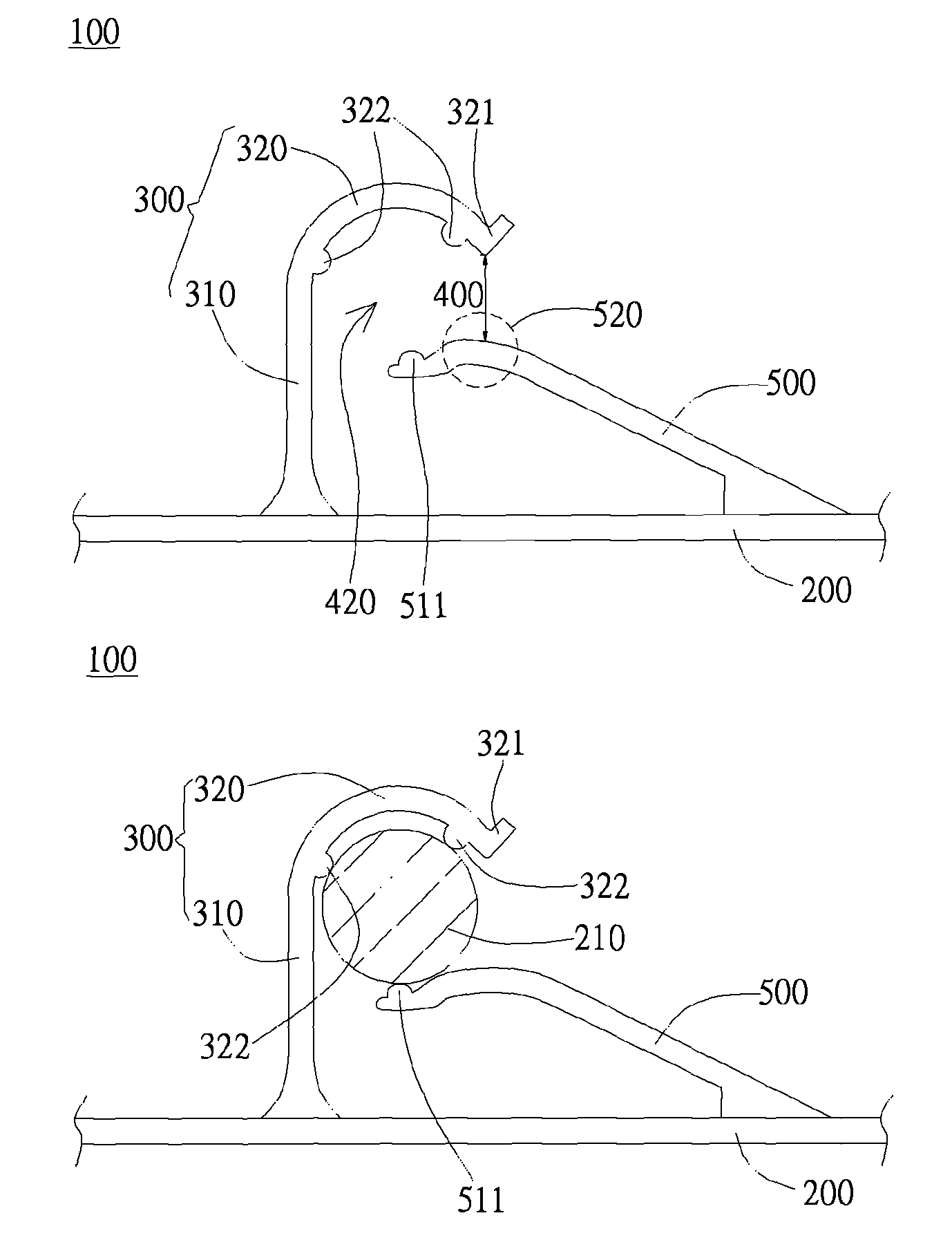
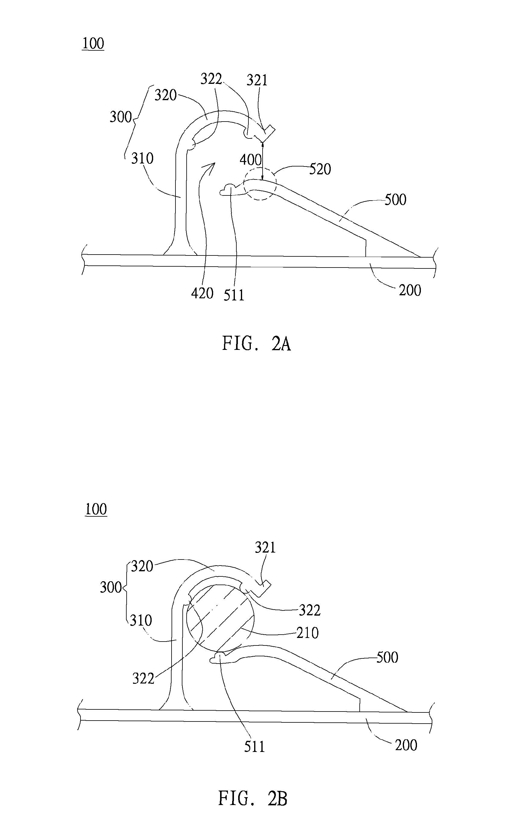
[0032]The present invention can be implemented in embodiments of different forms. The drawings and the contents below serve as explanation of preferred embodiments of the present invention. Please also understand that the present specification discloses exemplary embodiments of the present invention and does not intend to limit the present invention to the drawings or specific embodiments disclosed.

[0033]The present invention provides a lamp-positioning device for holding a lamp and maintaining the lamp at a fixed position. The lamp-positioning device preferably includes materials such as polycarbonate (PC) or acrylonitrile-butadiene-styrene (ABS), but is not limited thereto. The lamp-positioning device can also include plastic materials or other suitable materials. Furthermore, the lamp-positioning device of the present invention is preferably manufactured by injection molding or other molding processes. People of ordinary skill and knowledge in the field can select the appropriate...


PUM


Abstract

The present invention provides a lamp positioning device and a backlight module using the lamp positioning device for holding lamps. The lamp positioning device includes an upper arm and a lower arm, wherein a holding space is formed between the upper arm and the lower arm for accommodating the lamp. Furthermore, at least one of the upper arm and the lower arm has elasticity and thus can provide the lamp with resistance against shock in order to avoid being cracked or shattered.

Description

BACKGROUND OF THE INVENTION[0001]1. Field of the Invention[0002]The present invention relates to a lamp-positioning device and the backlight module using the same; most specifically to a lamp-positioning device used in a backlight module of a liquid crystal display.[0003]2. Description of the Prior Art[0004]In recent years, liquid crystal displays has become the mainstream in various types of display devices. Liquid crystal displays are extensively used in electronic products such as home televisions, monitors of personal computers and laptop computers, display screens of mobile phones and digital cameras. In liquid crystal displays, the backlight modules are used to provide bright and evenly distributed light for the liquid crystal display to display desired images. The backlight modules include edge-lighting backlight module and bottom-lighting backlight module respectively suitable for liquid crystal displays of different sizes.[0005]FIG. 1A and FIG. 1B illustrate a lamp-holding ...

Claims


Application Information

Patent Timeline
Patent Type & Authority Patents(United States)
IPC IPC(8): F21V7/04
CPCG02F1/133604G02F1/133608G09F13/04G09F13/18F21V19/009
Inventor CHEN, BEN-HON
Owner AU OPTRONICS CORP
Why Eureka
Try Eureka