
Coaxial cable connector

a technology of coaxial cable and connector, which is applied in the direction of connection, electrical apparatus, coupling device connection, etc., can solve the problems of high installation cost, structural arrangement drawbacks, and noise interference during signal transmission

Active Publication Date: 2012-12-11
LU YUEH CHIUNG
View PDF11 Cites 41 Cited by
  • Summary
  • Abstract
  • Description
  • Claims
  • Application Information

AI Technical Summary

Benefits of technology

[0008]The present invention has been accomplished under the circumstances in view. It is main object of the present invention to provide a coaxial cable connector for assembly with one of a series of coaxial cables having one same specification and different wire outer diameters, which eliminates the drawbacks of the aforesaid various prior art designs.
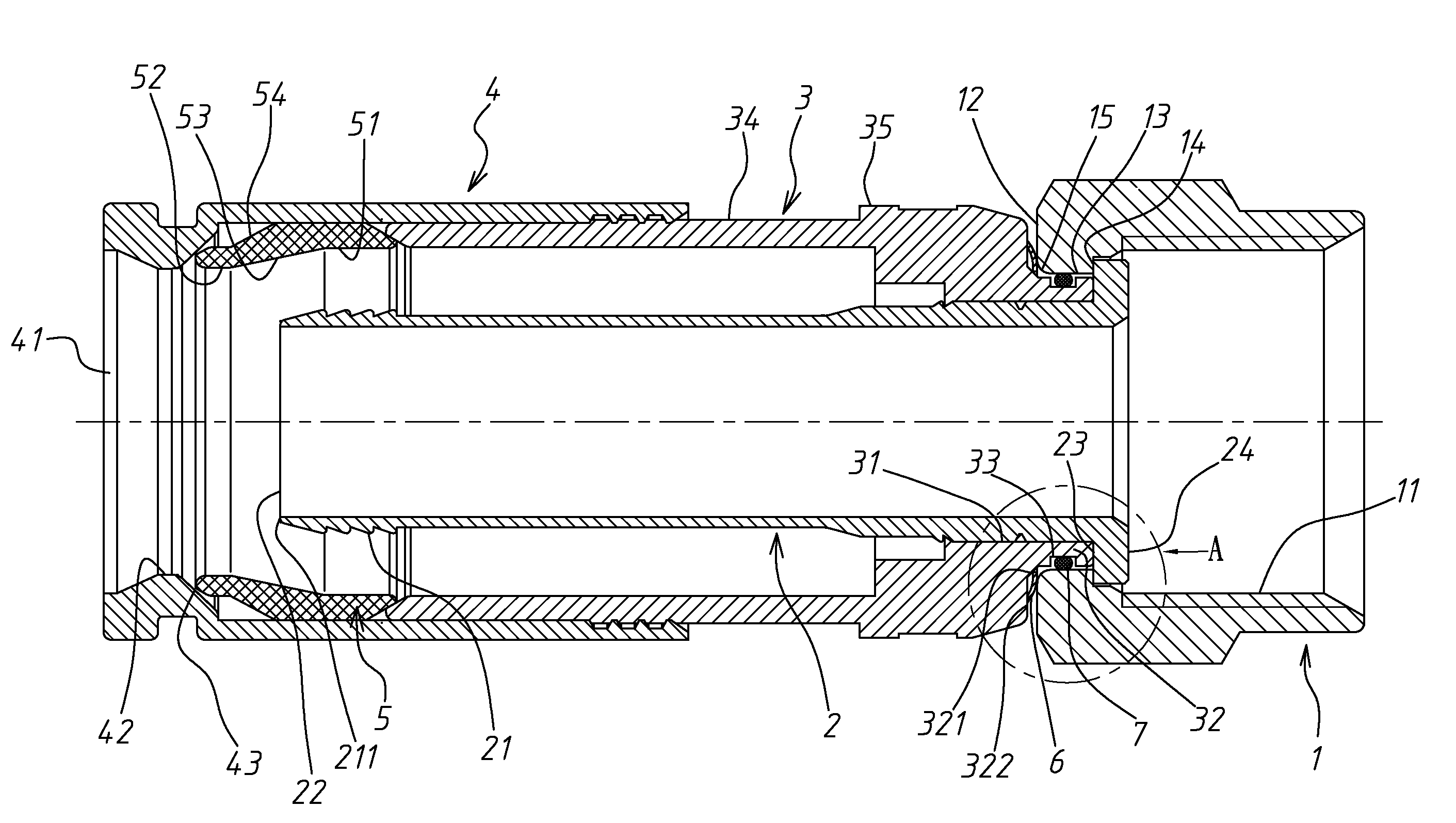
[0010]By means of attaching the curved spring plate to the front neck of the body shell to keep the back face of the curved spring plate in positive contact with the annular rear contact face of the screw nut, the inside stop face of the screw nut can be positively forced into contact with the annular front stop face of the inner tube for grounding when the screw nut and the mating device are fastened together to force the center conductor of the coaxial cable into engagement with the metal clamping plate of the mating device. Even if the inner thread of the screw nut is threaded onto only one thread turn of the outer thread of the F-connector of the mating member, the inner tube and the screw nut can be positively grounded with the mating device, maintaining signal transmission reliability. Further, the curved spring plate is symmetrical and easy and inexpensive to manufacture, and can be installed in either direction to assure a high level of contact stability.

Problems solved by technology

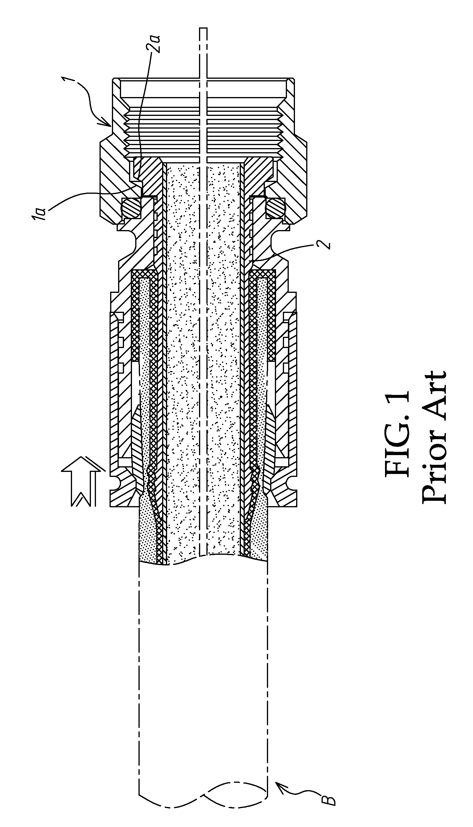
If the screw nut 1 is not fastened tight after installation, or the screw nut 1 is loosed after a long use, noise interference may occur during signal transmission.
However, the structural arrangement has the drawbacks of high installation cost, low spring force and instable contact.
Further, the installation of the spring plate 90 is limited to a particular direction.
Further, this spring plate 90 is specially designed, its fabrication cost is high.

Method used


Image

  • Coaxial cable connector
  • Coaxial cable connector
  • Coaxial cable connector

Examples


Embodiment Construction

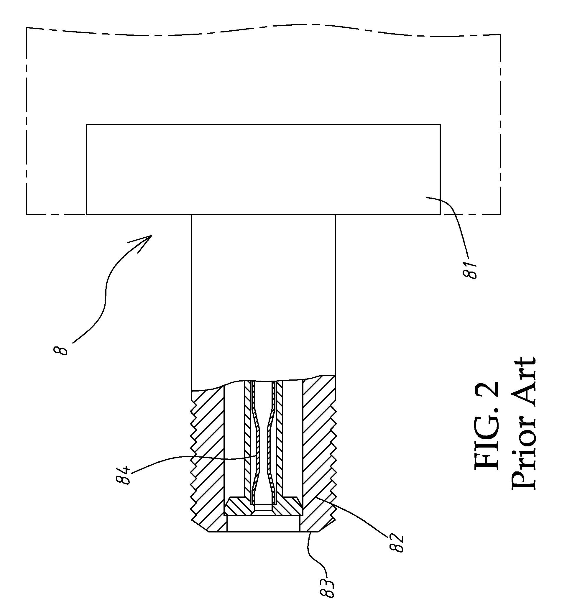
[0024]Referring to FIGS. 4˜7, a coaxial cable connector in accordance with a first embodiment of the present invention is substantially similar to “Coaxial cable connector” of U.S. patent application Ser. No. 13 / 015,572, and adapted for connecting a coaxial cable to a mating device (see FIG. 2). The coaxial cable connector comprises a screw nut 1, an inner tube 2, a body shell 3, a barrel 4, a plastic bushing 5, a curved spring plate 6 and an O-rig 7.

[0025]The screw nut 1 comprises an inner thread 11 for threading onto an outer thread of a F-connector 82 of a mating member 8 (see FIG. 2), a vertically (radially) extending annular rear contact face 12 disposed at the rear side thereof, as shown in FIGS. 6 and 7, a horizontally (axially) extending tubular rear inner face 13, an inside stop face 14 perpendicularly extended from the front side of the horizontally (axially) extending tubular rear inner face 13 in a parallel manner relative to the vertically (radially) extending annular r...


PUM


Abstract

A coaxial cable connector suitable for assembly with one of a series of coaxial cables having one same specification and different wire outer diameters is disclosed to use a plastic bushing for compressing by a barrel to wrap about the coaxial cable and compress an inner tube against the aluminum foil and insulation spacer of the coaxial cable, protecting the coaxial cable against weather and extending the lifespan, an O-ring in a locating groove around a front neck of a body shell or on an annular rear contact face of a screw nut to seal the gap between the screw nut and the body shell, and a curved spring plate for stoppage between an annular front stop face of the body shell and an annular rear contact face of the screw nut for grounding to enhance signal transmission reliability.

Description

BACKGROUND OF THE INVENTION[0001]1. Field of the Invention[0002]The present invention relates to coaxial cable connectors and more particularly, to such a coaxial cable for connecting a coaxial cable to a mating device, for example, cable TV signal line, maintaining excellent signal transmission.[0003]2. Description of the Related Art[0004]U.S. Pat. No. 8,011,955, invented by the present inventor and now allowed for patent, discloses a coaxial cable connector for assembly with one of a series of coaxial cables having one same specification and different wire outer diameters that uses a plastic bushing for compressing by a barrel to wrap about the coaxial cable and compress an inner tube against the aluminum foil and insulation spacer of the coaxial cable, protecting the coaxial cable against weather and extending the lifespan. A short distance is left between the aluminum foil insertion hole on the left end of the inner tube and the left orifice of the barrel, facilitating insertion...

Claims


Application Information

Patent Timeline
IPC IPC(8): H01R9/05
CPCH01R9/05H01R13/6584
Inventor LU, YUEH CHIUNG
Owner LU YUEH CHIUNG
Learn More