Ankle arthrodesis nail and outrigger assembly

a technology of arthrodesis nail and outrigger, which is applied in the field of surgical and bone fusion devices and systems, can solve the problems of wear or injury of the joint or interconnection of the lower end of the tibia, the fibula, and the talus, and achieve the effect of superior stability, reduced total length of the combined nail, and improved stability

Active Publication Date: 2012-12-11
ORTHOFIX SRL +2
View PDF497 Cites 37 Cited by
  • Summary
  • Abstract
  • Description
  • Claims
  • Application Information

AI Technical Summary

Benefits of technology

[0005]It is therefore a primary object of the invention to provide both an arthrodesis implant which is simple, easy to install and effective, as well as an arthrodesis outrigger assembly for use with such implant which is effective during an arthrodesis operation for proper alignment and implantation of the arthrodesis implant.
[0006]It is a still further object of the invention to provide an arthrodesis implant which can be relatively easily implanted in the foot and ankle and quickly, easily and effectively secured in place.
[0010]It is a still further object of the invention to provide an arthrodesis nail outrigger assembly wherein the outrigger assembly can be adjustably rotated around an arthrodesis with respect to a stationary intramedullary nail device.
[0011]It is a still further object of the invention to provide an arthrodesis nail outrigger assembly having a cannulated nail mounting shaft arrangement to allow for compression of a two-sectioned intramedullary nail device, resulting in a more tightly compressed and stable tibio-calcaneal arthrodesis.
[0013]An intramedullary fastener or nail is provided having which nail is formed in two sections which are adjustably joined together by an internal bolt member which can be rotated to decrease the total length of the combined nail and thus is capable of providing compression across an arthrodesis site in a tibio-calcaneal arthrodesis nailing procedure. After the nail has been inserted upwardly through holes drilled in the calcaneus and talus bones and tibia, using an outrigger assembly such nail is first secured to the tibia, after which the outrigger assembly in combination which a compression disc provided at the distal end of the nail is used to rotate the internal bolt member causing the distal or lower section of the nail and compression disc to move upwardly toward the proximal or upper section, providing compression of the calcaneus and talus bones with the tibia so that any spaces between the joints are closed prior to securing the bones in such position. In addition, an improved outrigger assembly is provided which enables the outrigger handle to be rotated and secured at ninety degree angles with respect to the stationary intramedullary nail, that also provides superior stability and ease of use, and having a cannulated nail mounting shaft which enables an adjustment to be inserted through the shaft upwardly into the nail to adjust the position of the bolt member and provide the desired amount of compression across the arthrodesis site. In addition, the amount of compression across the arthrodesis site can be adjusted at a later date via a minimally invasive procedure.

Problems solved by technology

In some patients the ankle joint or interconnection of the lower end of the tibia, the fibula, and the talus (spaced apart by articular cartilage and held together by various ligaments) can become worn or injured due to a degenerative condition or deformity, or a fracture, subluxation, or other traumatic event.
A limitation of known intramedullary or tibio-calcaneal arthrodesis nailing systems is in obtaining sufficient compression across the arthrodesis site so that a proper fusion is accomplished.

Method used


Image

  • Ankle arthrodesis nail and outrigger assembly
  • Ankle arthrodesis nail and outrigger assembly
  • Ankle arthrodesis nail and outrigger assembly

Examples


Embodiment Construction

[0037]The following detailed description is of the best mode or modes of the invention presently contemplated. Such description is not intended to be understood in a limiting sense, but to be an example of the invention presented solely for illustration thereof, and by reference to which in connection with the following description and the accompanying drawings one skilled in the art may be advised of the advantages and construction of the invention. The invention is intended to cover alternatives, modifications, and equivalents, which may be included within the spirit and scope of the invention as defined by the appended claims.

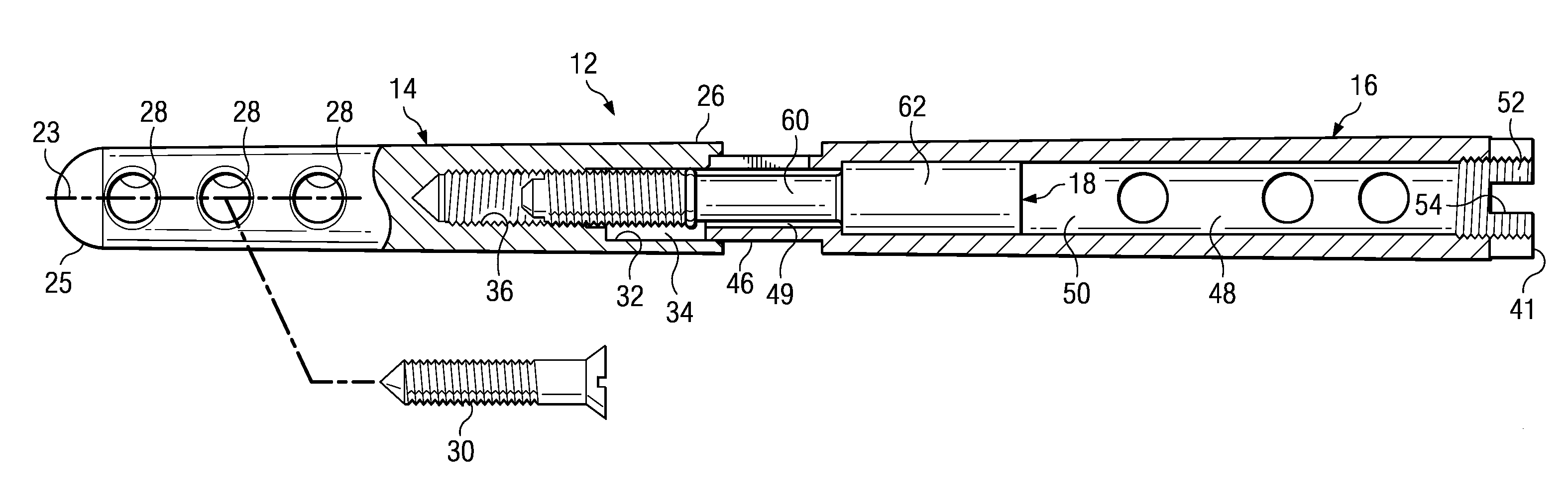
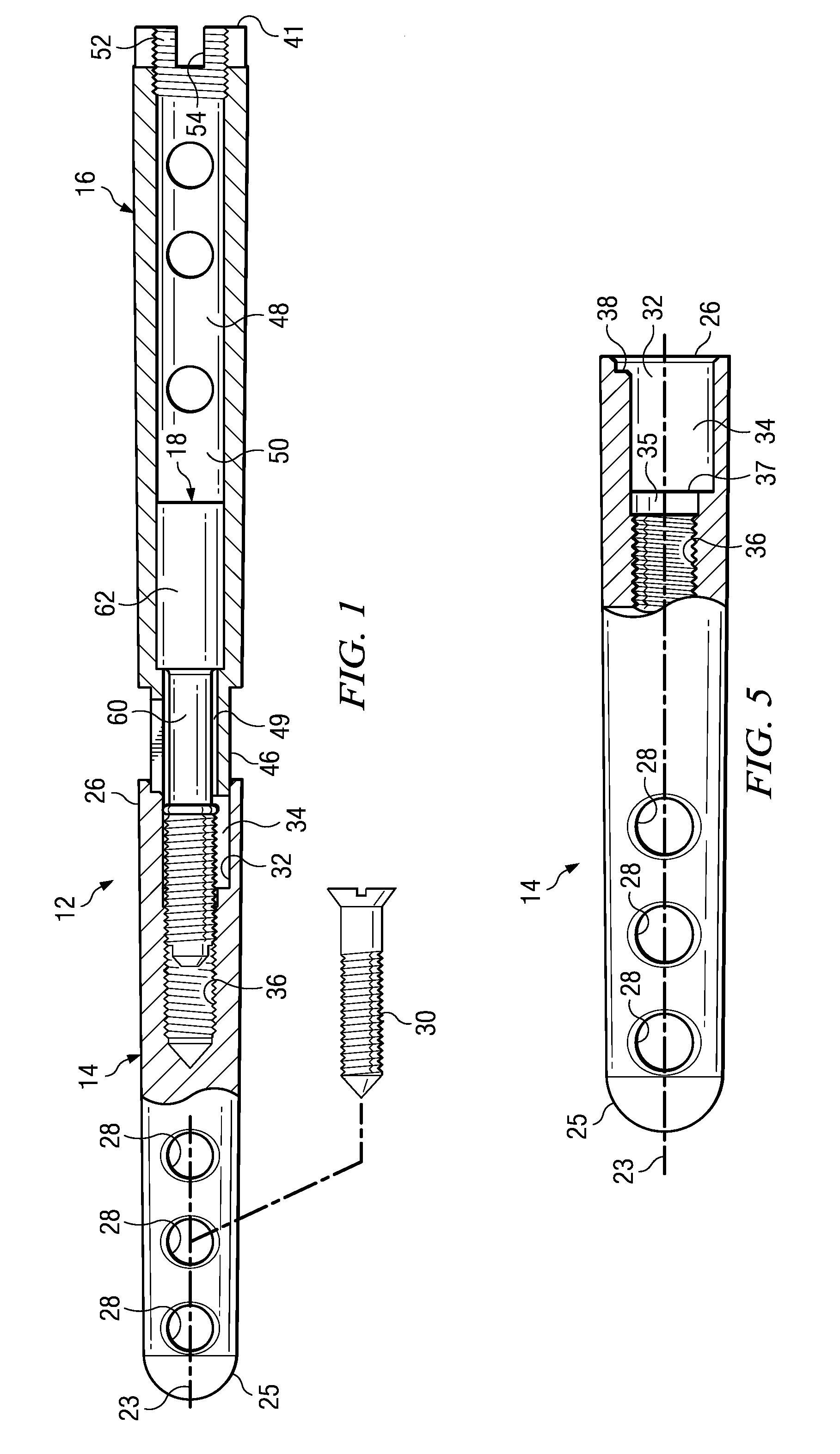
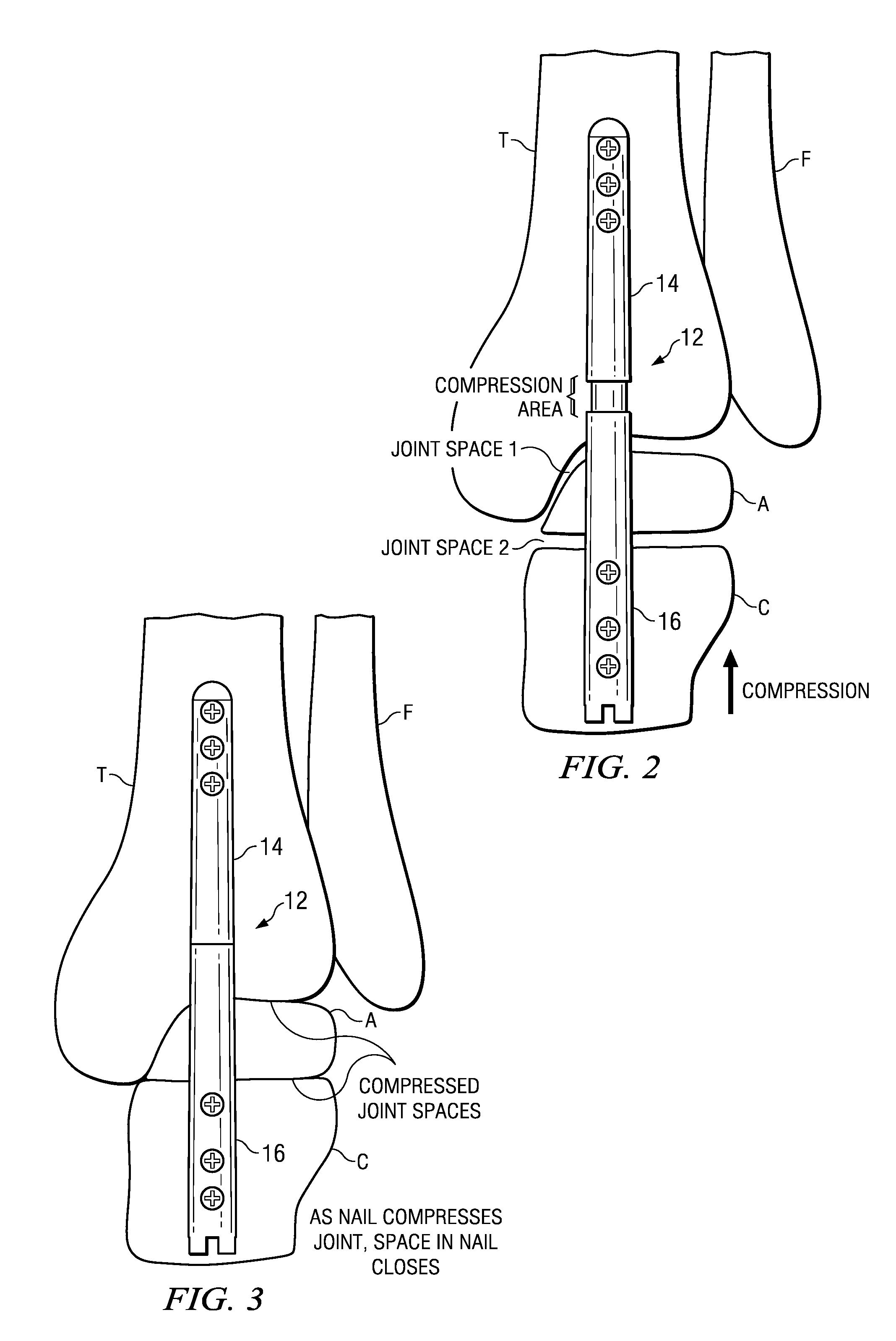
[0038]FIGS. 1-11 illustrate the intramedullary fixation device of the present invention, FIGS. 12-14 and 17 illustrate the combination intramedullary fixation device and outrigger assembly, and FIGS. 15-16 illustrate the outrigger assembly alone. Referring to FIG. 1, there is shown an embodiment of the intramedullary fixation device 12 of the present inventi...


PUM


Abstract

An intramedullary fixation device having a distal section; a proximal section; a connecting member for adjustably securing the distal and proximal sections end to end along a longitudinal axis; a screw securing the proximal section to a first bone; and a screw securing the distal section to a least one different bone. The connecting member is rotated to provide compression across a bone arthrodesis site to be stabilized and fused. Also described is a method of utilizing the intramedullary fixation device with an outrigger assembly.

Description

CROSS-REFERENCE TO RELATED APPLICATIONS[0001]This application claims priority to U.S. Provisional Application No. 61 / 079,132, filed on Jul. 9, 2008, entitled “ARTHRODESIS NAIL OUTRIGGER ASSEMBLY” and to U.S. Provisional Application No. 61 / 079,130 filed on Jul. 9, 2008, entitled “ANKLE ARTHRODESIS NAIL AND OUTRIGGER ASSEMBLY” which are incorporated herein by reference in their entirety as if set forth in full.FIELD OF THE INVENTION[0002]The present invention relates to surgical and bone fusion devices and systems in general, and more particularly to an improved arthrodesis nail that enables the bone fusion site to be sufficiently compression prior to fusion, and more particularly still to an improved outrigger assembly and method for implanting an arthrodesis nail.BACKGROUND OF THE INVENTION[0003]The lower limbs of the human body, namely the femur (thigh bone), the tibia (shinbone), and fibula, are designed to bear the weight of the body and to provide the body with sufficient stabil...

Claims


Application Information

Patent Timeline
Patent Type & Authority Patents(United States)
IPC IPC(8): A61B17/56A61B17/88
CPCA61B17/1725A61B17/7225A61B2017/1775A61B17/7291A61B17/7233A61B17/1775
Inventor BRIGIDO, STEPHEN
Owner ORTHOFIX SRL
Why Eureka
Try Eureka