Air pump pressure gauge

a pressure gauge and air pump technology, applied in the direction of fluid pressure measurement by mechanical elements, fluid pressure measurement using pistons, instruments, etc., can solve the problems of limited structural size, small window, and inability to facilitate viewing of readings

Active Publication Date: 2012-12-25
BETO ENG & MARKEITNG
View PDF23 Cites 9 Cited by
  • Summary
  • Abstract
  • Description
  • Claims
  • Application Information

AI Technical Summary

Benefits of technology

[0017]The present invention has been accomplished under the circumstances in view. It is the main object of the present invention to provide an air pump pressure gauge, which is kept inside the body of the air pump to indicate the pressure value clearly without interfering with the pumping operation, allowing the user to view and read the readings conveniently.

Problems solved by technology

In a conventional air pump with an analog pressure gauge, the analog pressure gauge is attached to the outside of the housing of the air pump that may interfere with the user's operation in pumping the air pump.
Due to the limitation of the outer diameter of the air pump, the view window is small, not facilitating viewing of the readings.
Due to this installation limitation, the structural size is limited.
The pressure value indication of U.S. Pat. No. 3,981,625 is large enough for easy reading without interfering with the pumping operation, however, it does not allow measurement of the pressure during pumping.
This design is inconvenient to use.

Method used


Image

  • Air pump pressure gauge
  • Air pump pressure gauge
  • Air pump pressure gauge

Examples


Embodiment Construction

[0030]Three examples of the invention will be described hereinafter for understanding of the spirit and scope of the invention.

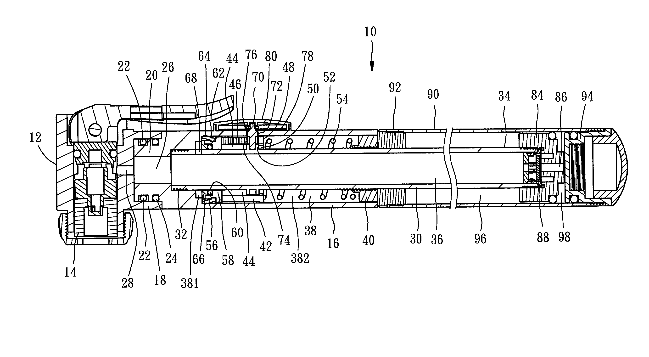
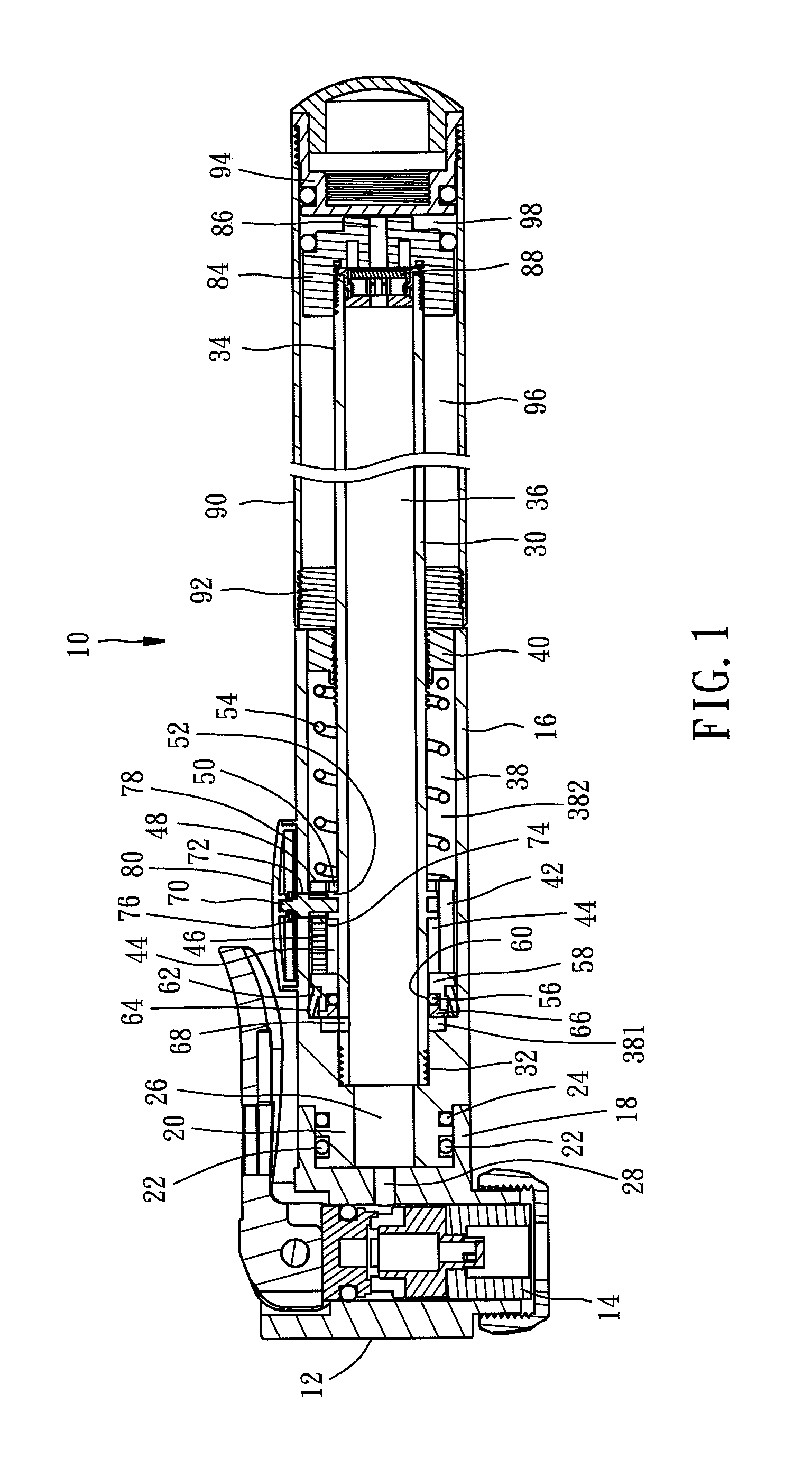
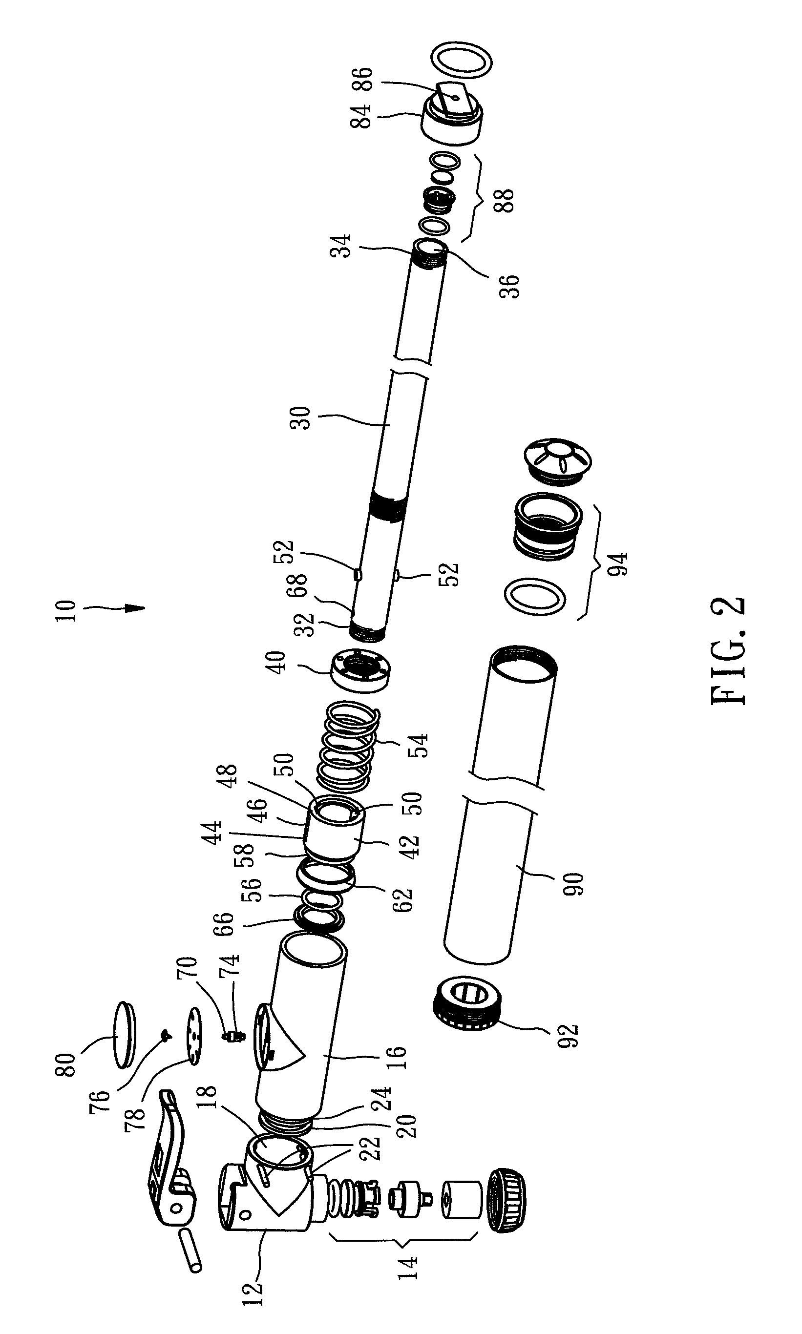
[0031]Referring to FIGS. 1 and 2, a handheld air pump 10 in accordance with a first embodiment of the invention is shown comprising:

[0032]a pump head 12 holding therein an air nozzle assembly 14, which is a known design and therefore no further description in this regard is necessary, having a coupling portion 18 located on one side thereof;

[0033]a casing 16 shaped like a tube and fixedly connected to the pump head 12, having a connection end portion 20 located on its one end and mounted with an O-ring 24 and then fastened to the coupling portion 18 of the pump head 12 with two pins 22 and defining therein an axial through hole 26 in communication with an air hole 28 in the coupling portion 18 of the pump head 12;

[0034]an inner tube 30 having one end 32 thereof coaxially fastened to the inside of the connection end portion 20 of the casing 16, two protrusion...


PUM

PropertyMeasurementUnit
forceaaaaaaaaaa
transparentaaaaaaaaaa
pressure measurementaaaaaaaaaa

Abstract

An air pump pressure gauge includes a casing, an inner tube coaxially affixed to the casing and defining with the casing an accommodation chamber, a movable member movable back and forth in the accommodation chamber, an end cap end cap set between the inner tube and the casing to seal one end of the accommodation space, a spring member stopped between the end cap and the movable member, at least one seal member mounted on the movable member to define a first airtight structure between the outer surface of the inner tube and the at least one seal member and a second airtight structure between the inside wall of the casing and the at least one seal member, an air hole in communication between the axial hole of the inner tube and the accommodation space, a longitudinal sliding slot located on the movable member, a rack extending along one side of the longitudinal sliding slot, a rotating axle inserted through the longitudinal sliding slot and having its inner end pivoted to the inner tube and its outer end extending out of the casing and a middle part thereof mounted with a gear being meshed with the rack, a pointer fixedly connected to the outer end of the rotating axle outside the casing, a graduation scale mounted on the casing below the pointer, and a transparent cover covering the graduation scale and the pointer.

Description

BACKGROUND OF THE INVENTION[0001]1. Field of the Invention[0002]The present invention relates to a pressure measurement apparatus and more specifically, to an air pump pressure gauge.[0003]2. Description of the Related Art[0004]Many prior art designs of air pump with pressure gauge are known. Exemplars are seen.[0005]U.S. Pat. No. 3,981,625 discloses an air pump in which a transparent handle and a piston are configured to form a pressure gauge.[0006]U.S. Pat. No. 5,779,457 discloses a view window type pressure gauge.[0007]U.S. Pat. No. 6,132,189 discloses an attached pressure gauge.[0008]U.S. Pat. No. 6,196,807B1 also discloses a view window type pressure gauge.[0009]US2002 / 0174723A1 discloses an electronic pressure gauge.[0010]US2004 / 0001761A1 discloses an attached analog pressure gauge.[0011]US2008 / 0056922A1 discloses an analog pressure gauge.[0012]U.S. Pat. No. 4,136,560 discloses a pressure gauge.[0013]In a conventional air pump with an analog pressure gauge, the analog pressure...

Claims


Application Information

Patent Timeline
Patent Type & Authority Patents(United States)
IPC IPC(8): G01L7/16
CPCF04B33/005
Inventor WANG, LOPIN
Owner BETO ENG & MARKEITNG
Why Eureka
Try Eureka