Adjustment element

a technology of adjustment element and adjustment bolt, which is applied in the direction of washers, screws, couplings, etc., can solve the problems of hollow bolt not being able to adjust further, the hollow bolt must always be loosened, and the fastening bolt cannot be loosened

Active Publication Date: 2012-12-25
BOLLHOFF VERBINDUNGSTECHNIK GMBH
View PDF21 Cites 33 Cited by
  • Summary
  • Abstract
  • Description
  • Claims
  • Application Information

AI Technical Summary

Benefits of technology

[0008]Using the embodiment of the adjustment element according to the invention an independent positioning of a fastened component is possible in the z direction and in the xy plane. The z position is adjusted by rotating the hollow bolt, whereby the holder of the component can be positioned in the z direction in a targeted manner using the outer thread of the hollow bolt and / or using the thread pairing of the hollow bolt and inner element. The z positioning can also occur when the component is fastened in its xy position. The xy position is fixed using a fastening means and the inner element of the adjustment element. The present design simultaneously makes it possible that the xy position of the component can be modified with a z position that is not to be changed. For this purpose, the fastening means, which fixes the inner element, is loosened. Then, the hollow bolt can be moved laterally relative to the fastening means, without change to the adjusted z position. After the new xy position has been adjusted, a renewed fixing of the inner element and therefore also of the hollow bolt occurs using the fastening means.
[0009]According to one embodiment, the inner element is fastened within the hollow bolt using a latching. Such a latching guarantees a fastening of the hollow bolt to the inner element that is without play, while at the same time, the hollow bolt can be rotated about its longitudinal axis. Thereby, adjusting a z position—that is, in the longitudinal direction of the hollow bolt—is guaranteed in that the holder of the component to be fastened is screwed onto the outer threads of the hollow bolt up to the desired position.
[0014]According to a further alternative of the adjustment element, the outer diameter of the washer is smaller than a diameter of the through opening of the hollow bolt, and / or a diameter of a through opening of the inner element is larger than a diameter of the fastening means so that, using the differences in the diameters, a maximum lateral positioning travel of the adjustment element can be established.
[0015]Because the fastening means, for example a fastening bolt, is fixed in its xy position, the difference between the diameter of the fastening means and the inner diameter of the inner element determines the maximum lateral positionability or adjustability of the inner element or of the adjustment element around the position of the fastening means. Furthermore, it can be applicable that the maximum lateral positioning travel of the adjustment element is determined by the difference between the diameter of the through opening of the hollow bolt and the outer diameter of the washer. As soon as the outside of the washer contacts the inner wall of the hollow bolt during positioning in the xy plane, the maximum lateral positioning travel of the adjustment element has been exhausted. This way, it is possible to determine the maximum lateral positioning travel of the adjustment element by targeted dimensioning of the diameter of the fastening means, of the inner diameter of the inner element, the outer diameter of the washer, and the inner diameter of the hollow bolt.

Problems solved by technology

Therefore, on the one hand, the hollow bolt is no longer accessible for further adjustment, and additionally movement of the hollow bolt is prevented by fastening the fastening bolt.
It is therefore disadvantageous with this design that for readjustments of the z position and respectively the hollow bolt, the fastening bolt must always be loosened.
High costs are connected with this high installation and maintenance effort.

Method used


Image

  • Adjustment element
  • Adjustment element
  • Adjustment element

Examples


Embodiment Construction

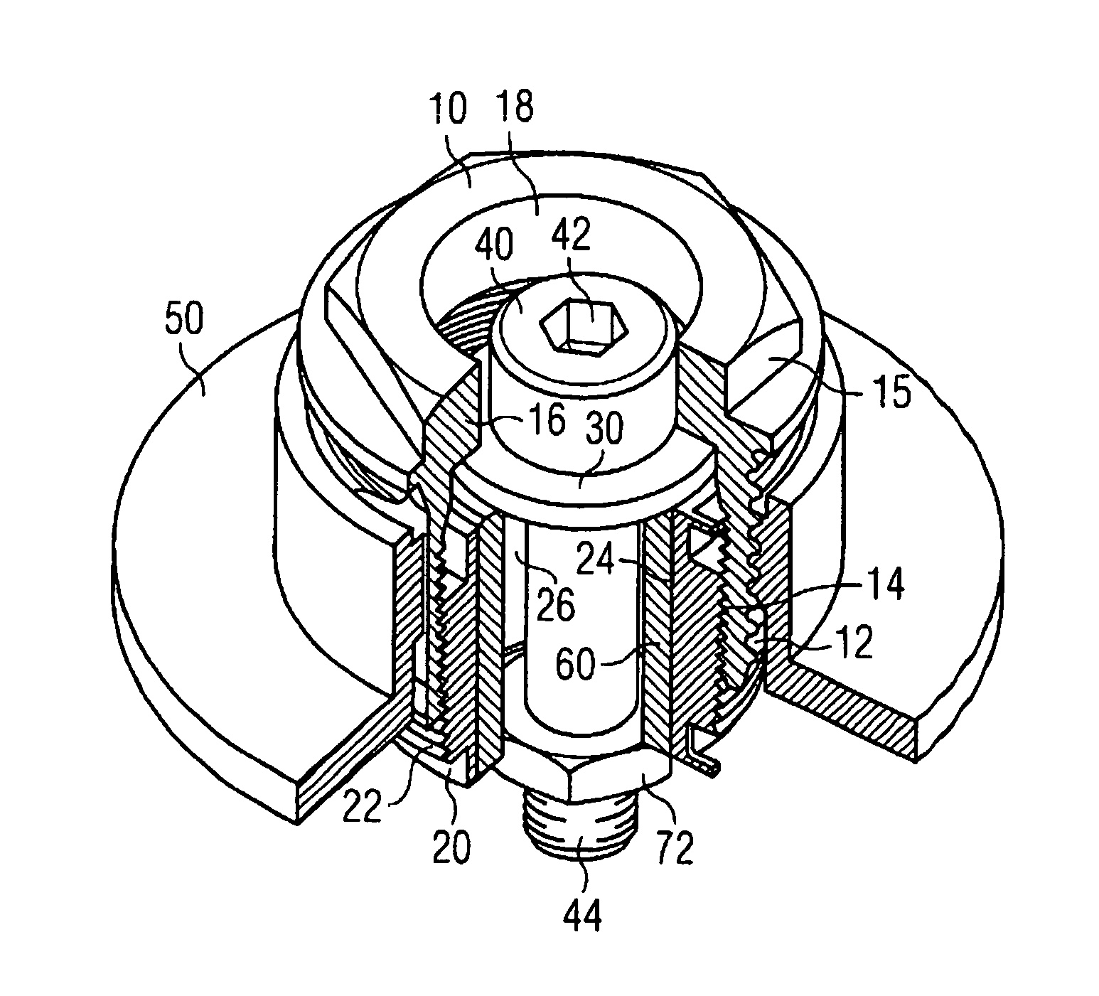
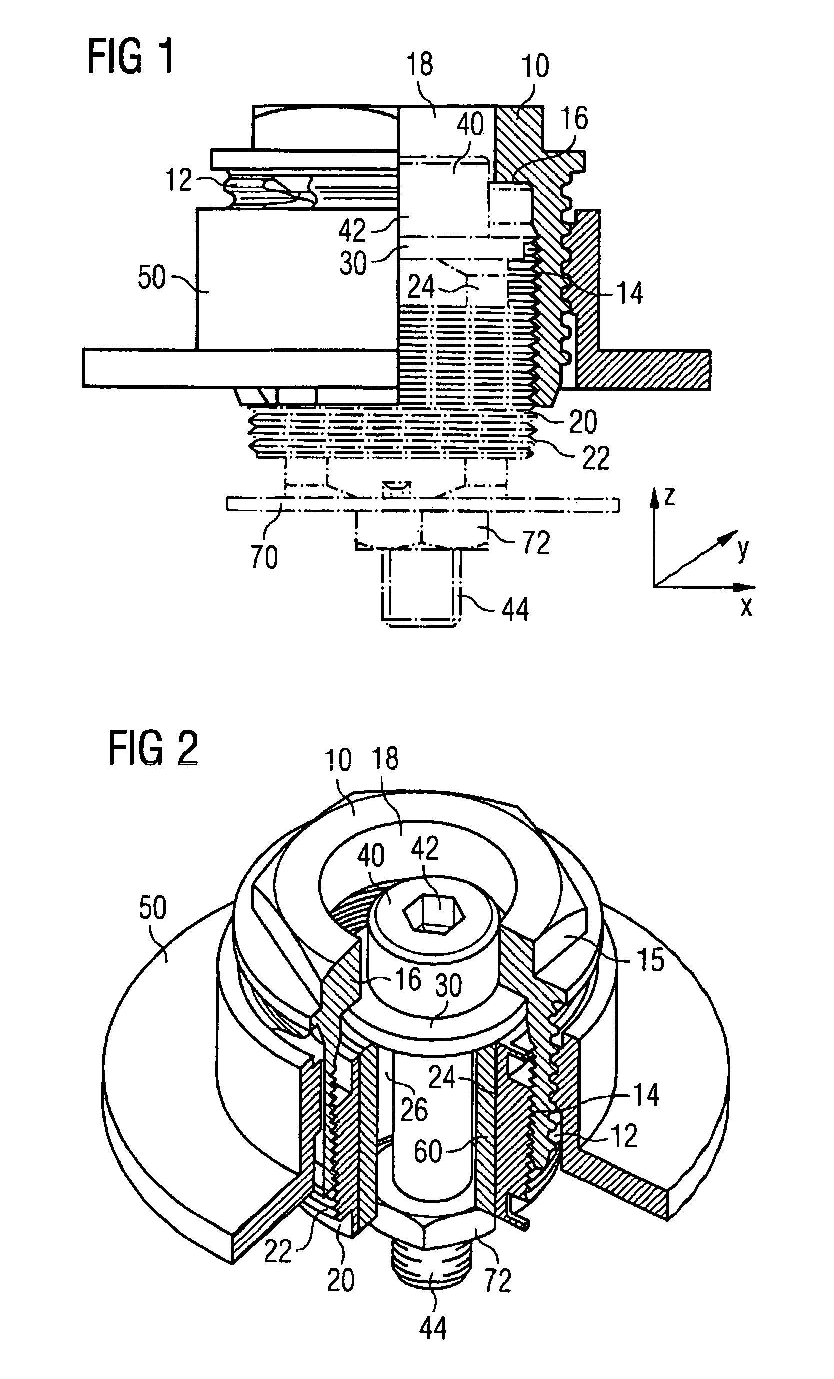
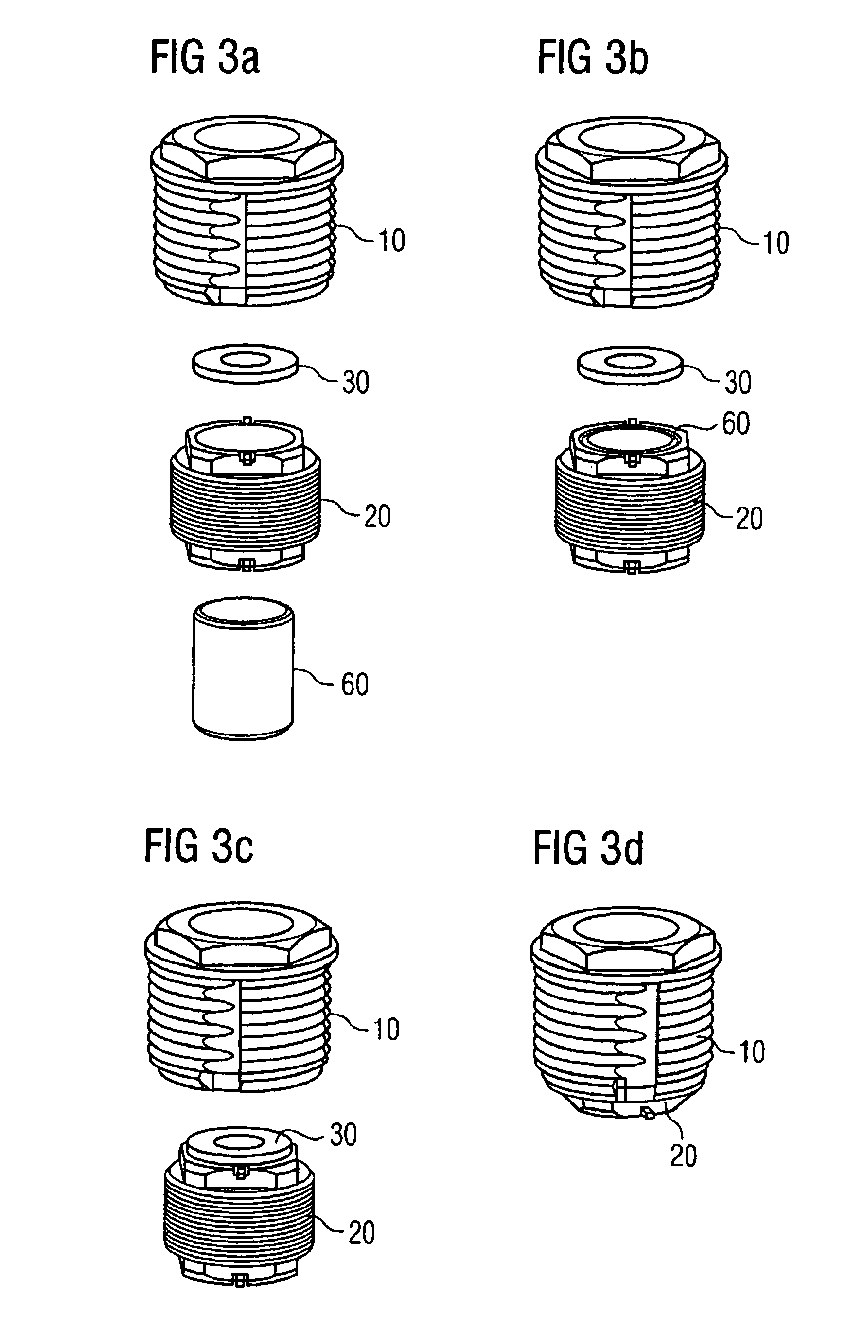
[0023]FIG. 1 shows a preferred embodiment of the adjustment element 1 according to the invention in a lateral partial sectional view. The adjustment element 1 comprises a hollow bolt 10, and inner element 20 and a washer 30. It is used for fixing and positioning any arbitrary component, for example a headlight in vehicle manufacturing, in space, that is, in the x, y and z direction. The headlight must be fastened during its installation in the auto body 70 of the vehicle. For this, the headlight must be positioned such that the requirements on the gap dimensions between the headlight and the auto body parts are fulfilled, especially on the outside of the vehicle. This requires a targeted positioning and fastening in all three spatial directions.

[0024]The component to be fastened and positioned, exemplified here by the headlight, comprises a holder 50. The holder 50 is fastened to the adjustment element 1, and adjusted in the z direction using an outer thread 12 of the hollow bolt 10...


PUM


Abstract

The present invention provides an adjustment element 1 with which a component can be fastened and can be positioned in space. The adjustment element has the following features: a banjo bolt 10 with an external thread 12 with which the component holder 50 can be positioned in the axial direction of the banjo bolt 10, an inner element 20 which is arranged within the banjo bolt 10 and to which the banjo bolt 10 is rotatably fastened, and a washer 30 which is held between the banjo bolt 10 and inner element 20 in a manner such that it can be laterally displaced in the axial direction of the inner element 20 such that the adjustment element 1 can be laterally positioned and can be fixed with a fastening means 40 reaching through the washer 30.

Description

[0001]This application is a U.S. National Phase of International Patent Application Serial No. PCT / EP2008 / 008811, filed Oct. 17, 2008 which claims priority to German Patent Application No. 20 2007 016 945.0 filed Dec. 5, 2007.FIELD OF THE INVENTION[0002]The present invention relates to an adjustment element with which a component can be fastened and can be positioned in space, i.e., its position in the x, y, and z direction can be selected and fixed.BACKGROUND OF THE INVENTION[0003]In the state of the art, such adjustment elements are used, for example for fastening headlights in motor vehicle manufacturing. During the installation of the headlights, a fastening and a targeted positioning of the headlight is necessary. To implement this, known adjustment elements consist of a hollow bolt, a fastening bolt with washer and a blind rivet nut, which is fastened in an auto body sheet.[0004]The hollow bolt of the adjustment element is screwed into a fastening eye of the headlight correspo...

Claims


Application Information

Patent Timeline
Patent Type & Authority Patents(United States)
IPC IPC(8): F16B43/00
CPCB60Q1/0433B60Q1/045F16B5/0233F16B5/0225Y10T403/75
Inventor STEFFENFAUSEWEH, SANDRAVORDERWISCH, ALEXANDERWELZEL, GERALD
Owner BOLLHOFF VERBINDUNGSTECHNIK GMBH
Why Eureka
Try Eureka