
Adapter for a compressed air filter and use of the same

a technology of compressed air and adapter, which is applied in the direction of cartridge filters, dispersed particle filtration, and using liquid separation agents, can solve the problems of restricting flow relationships in the filter connection housing, and achieves the effect of favorable flow conduction and simple and reliable connection of the filter elemen

Active Publication Date: 2012-12-25
KAESER KOMPRESSOREN SE
View PDF18 Cites 4 Cited by
  • Summary
  • Abstract
  • Description
  • Claims
  • Application Information

AI Technical Summary

Benefits of technology

The present invention provides a compressed air filter adapter that allows for a simple and reliable connection of a filter element to a filter connection housing and promotes favorable flow conduction within the housing. The adapter has a flow duct enclosed by a wall for compressed air, with the duct being delimited at a first end by a first opening and at a second end by a second opening. The inner contour of the first opening and the inner contour of the second opening are offset from each other in an offset direction, resulting in a displaced surface center of gravity of the first opening in relation to the second opening. The outer contour of the first opening is symmetrical to a center line, and the outer contour is configured to be completely convex or inside the inner contour. The technical effects of the invention include improved flow conduction, simplified and reliable connection, and improved adhesion between the filter element and the housing.

Problems solved by technology

Since due to its filtering function, the filter element clogs over extended operating times, that is to say dirt particles are captured within the filter element, it has to be replaced at defined or variable maintenance intervals.
However, restricted flow relationships may form in the filter connection housing due to the various target settings such as a space-saving installation into the line conducting the compressed air to be filtered, accessibility to the filter element, and reliable sealing between the filter element and the filter connection housing.

Method used


Image

  • Adapter for a compressed air filter and use of the same
  • Adapter for a compressed air filter and use of the same
  • Adapter for a compressed air filter and use of the same

Examples


Embodiment Construction

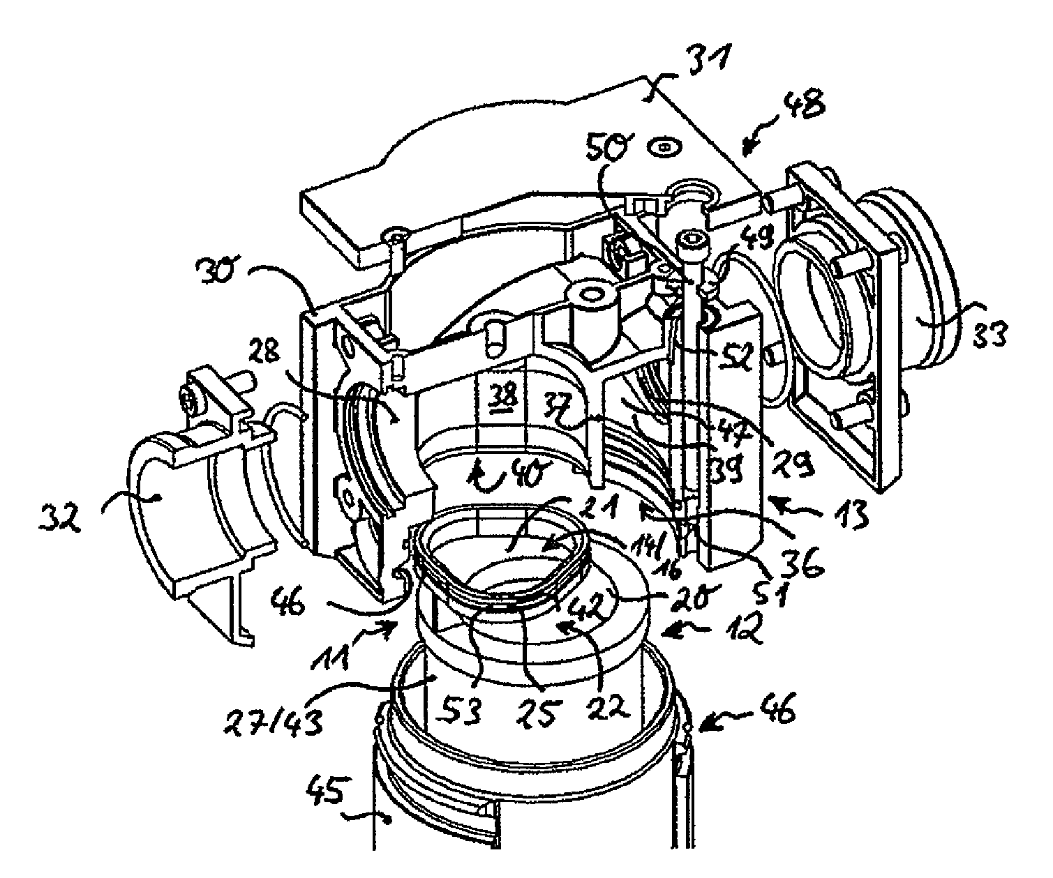
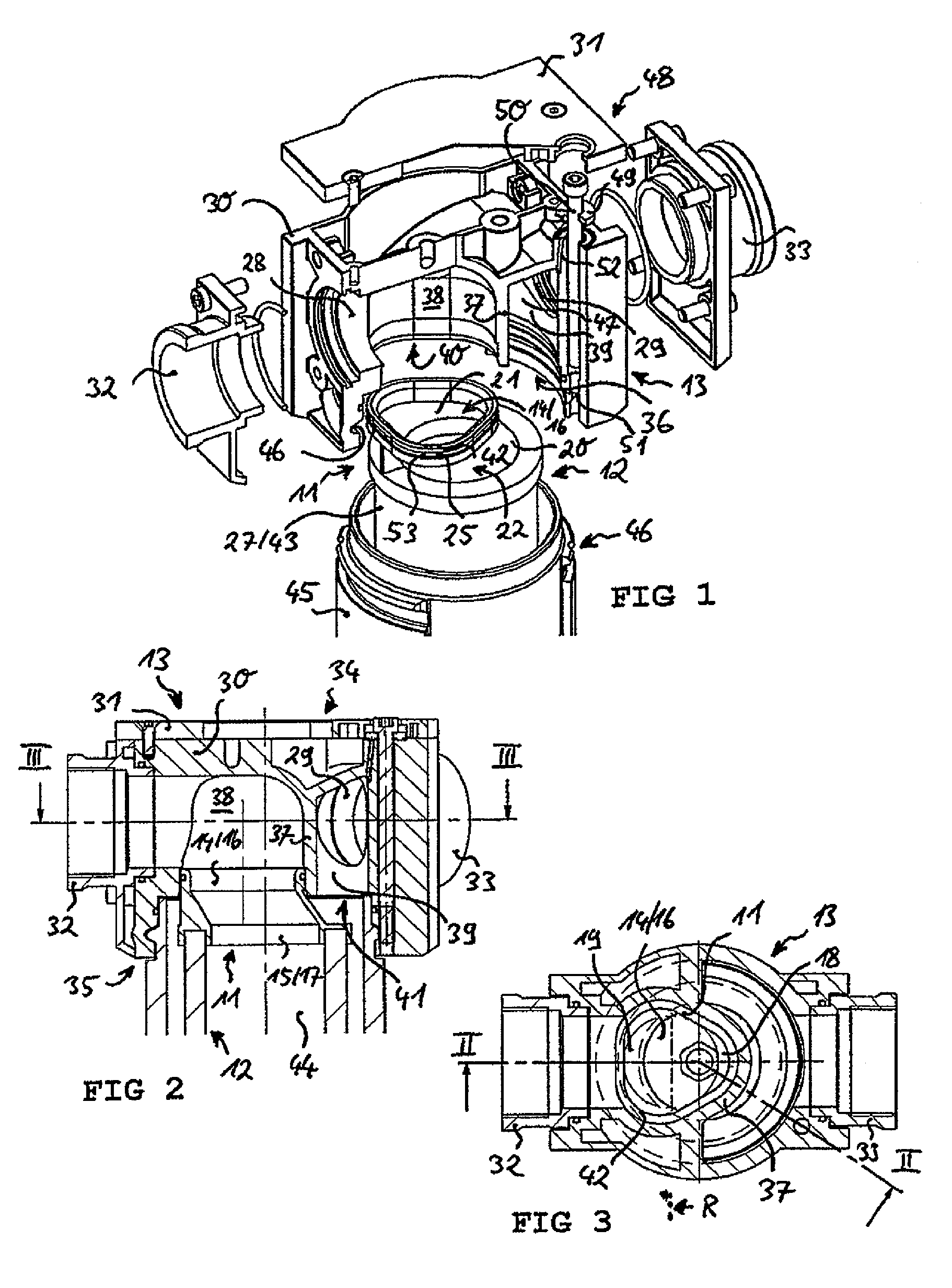
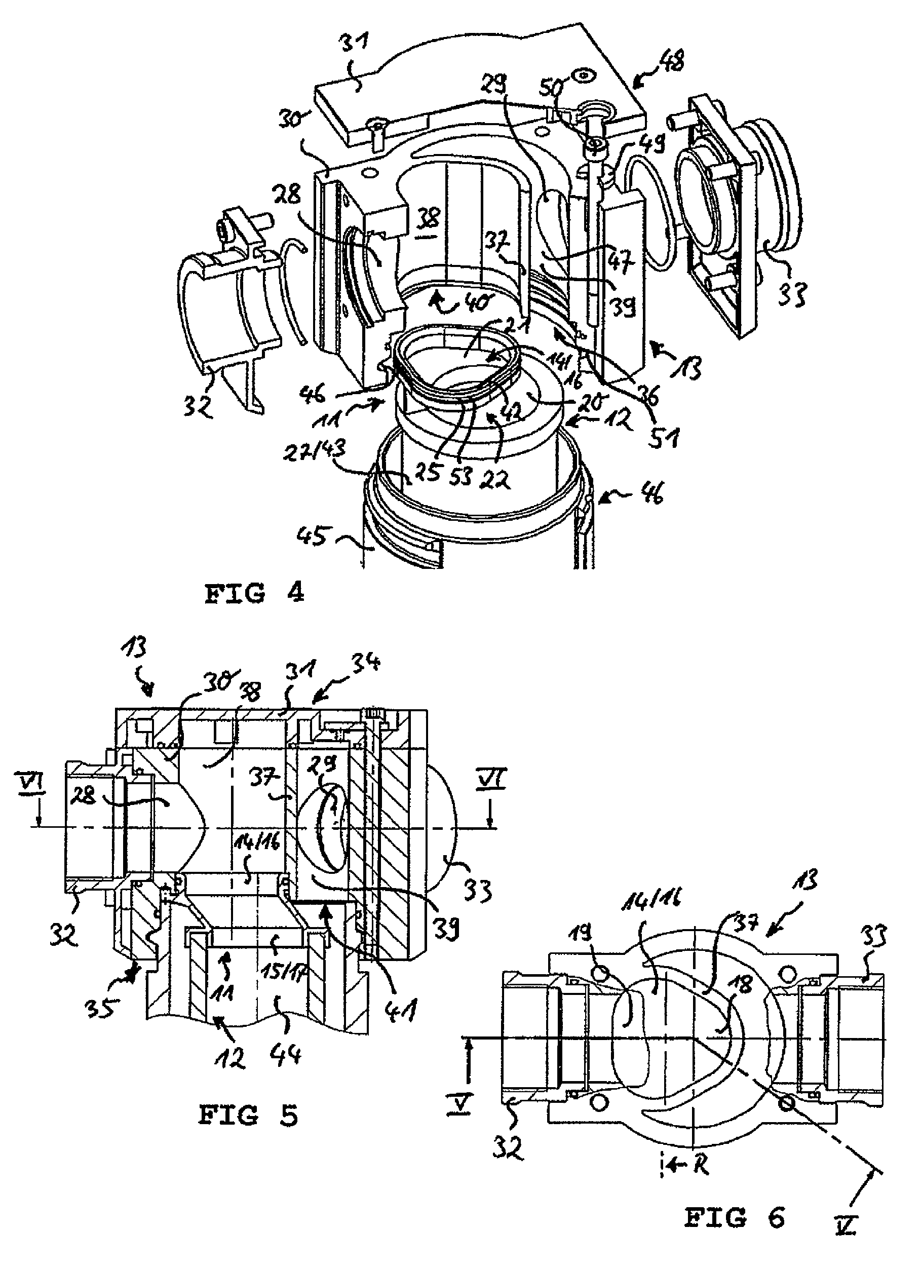
[0061]In FIG. 1, an embodiment of a filter arrangement according to the invention is illustrated in a perspective exploded view. The filter arrangement first of all comprises a filter connection housing 13 having a first flow opening 28 and a second flow opening 29. In one specific configuration, the first flow opening 28 of the filter connection housing 13 may define an inflow opening, and the second flow opening 29 of the filter connection housing 13 may define an outflow opening. The through-flow direction, however, could also be inverse.

[0062]The filter connection housing 13 in the present embodiment consists of a base body 30, a cover 31 provided on an upper side 34, and two connection flanges 32, 33 on the first flow opening 28 and the second flow opening 29 respectively for connection to a compressed fluid line or for connecting a further component through which flows compressed fluid, e.g. a further filter element.

[0063]At a lower side 35 opposite the upper side 34, the filt...


PUM

PropertyMeasurementUnit
center of gravityaaaaaaaaaa
gravityaaaaaaaaaa
lengthaaaaaaaaaa

Abstract

A compressed air filter adapter for connecting a filter element (12) to a filter connection housing (13) includes a flow duct (21) enclosed by a wall (20) for compressed air, the flow duct (21) at a first end being delimited by a first opening (14), having an inner contour (142) defined by a first edge (141) and an outer contour (143), and at a second end by a second opening (15), having an inner contour (152) defined by a second edge (151) and an outer contour (153). The first opening (14) is provided for connection to a filter connection housing (13) and forms an opening cross-section (16), defined by the inner contour (142) of the first opening (14). The second opening (15) defines an opening on the filter side and forms a second opening cross-section (17), defined by the inner contour (152) of the second opening (15).

Description

CROSS-REFERENCE TO RELATED APPLICATIONS[0001]This application is a Section 371 of International Application No. PCT / EP2008 / 052540, filed Feb. 29, 2008, which was published in the German language on Sep. 12, 2008, under International Publication No. WO 2008 / 107412 A1 and the disclosure of which is incorporated herein by reference.BACKGROUND OF THE INVENTION[0002]The invention relates to a compressed air filter adapter for connecting a filter element to a filter connection housing, wherein the adapter has a flow duct enclosed by a wall for compressed air, wherein the flow duct is delimited at a first end by a first opening having an inner contour defined by a first edge and an outer contour, and at a second end by a second opening having an inner contour defined by a second edge and an outer contour, wherein the first opening is provided for connection to a filter connection housing and forms an opening cross-section defined by the inner contour of the first opening, and wherein the s...

Claims


Application Information

Patent Timeline
Patent Type & Authority Patents(United States)
IPC IPC(8): B01D46/00
CPCB01D46/0005B01D46/0041B01D46/2411Y10T29/49826B01D2201/34B01D2265/05B01D2201/291
Inventor FEISTHAUER, MICHAELFISCHER, NORBERTLEIDNER, GERHARDBAR, NORBERT
Owner KAESER KOMPRESSOREN SE
Learn More