
System and method for image demosaicing

a demosaicing and image technology, applied in the field of image processing, can solve the problems of only being able to determine a color, using two interpolation directions (i.e., horizontal and vertical), and limited digital sensors, so as to achieve less homogeneity noise, improve image quality, and reduce zippering artifacts.

Active Publication Date: 2012-12-25
CISCO TECH INC
View PDF6 Cites 42 Cited by
  • Summary
  • Abstract
  • Description
  • Claims
  • Application Information

AI Technical Summary

Benefits of technology

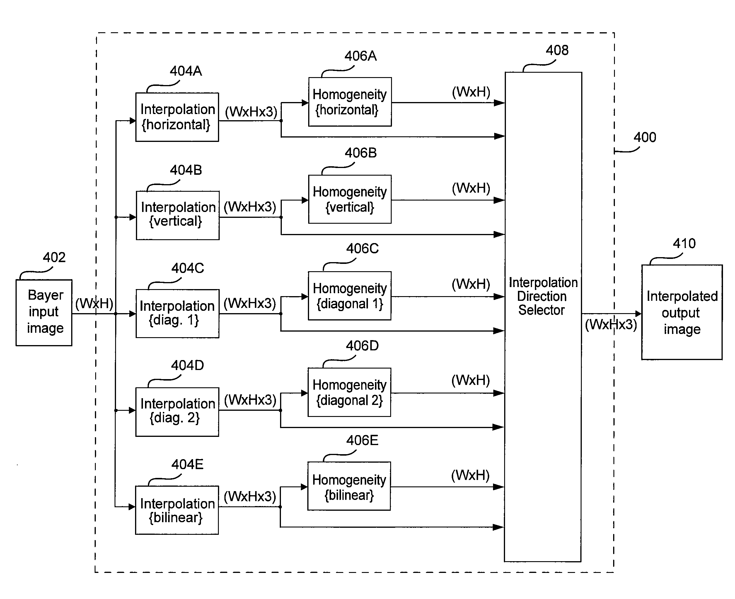
[0018]One advantage of the systems and methods is that better image quality is achieved when compared to using prior art techniques. Zippering artifacts are especially reduced along diagonal edges in the image. Also, since the homogeneity neighborhoods include the same pixel locations as the corresponding interpolation regions, less homogeneity noise is introduced into the interpolation direction selection process. Accordingly, better image quality is achieved by choosing the most appropriate interpolation direction for a given pixel location.

Problems solved by technology

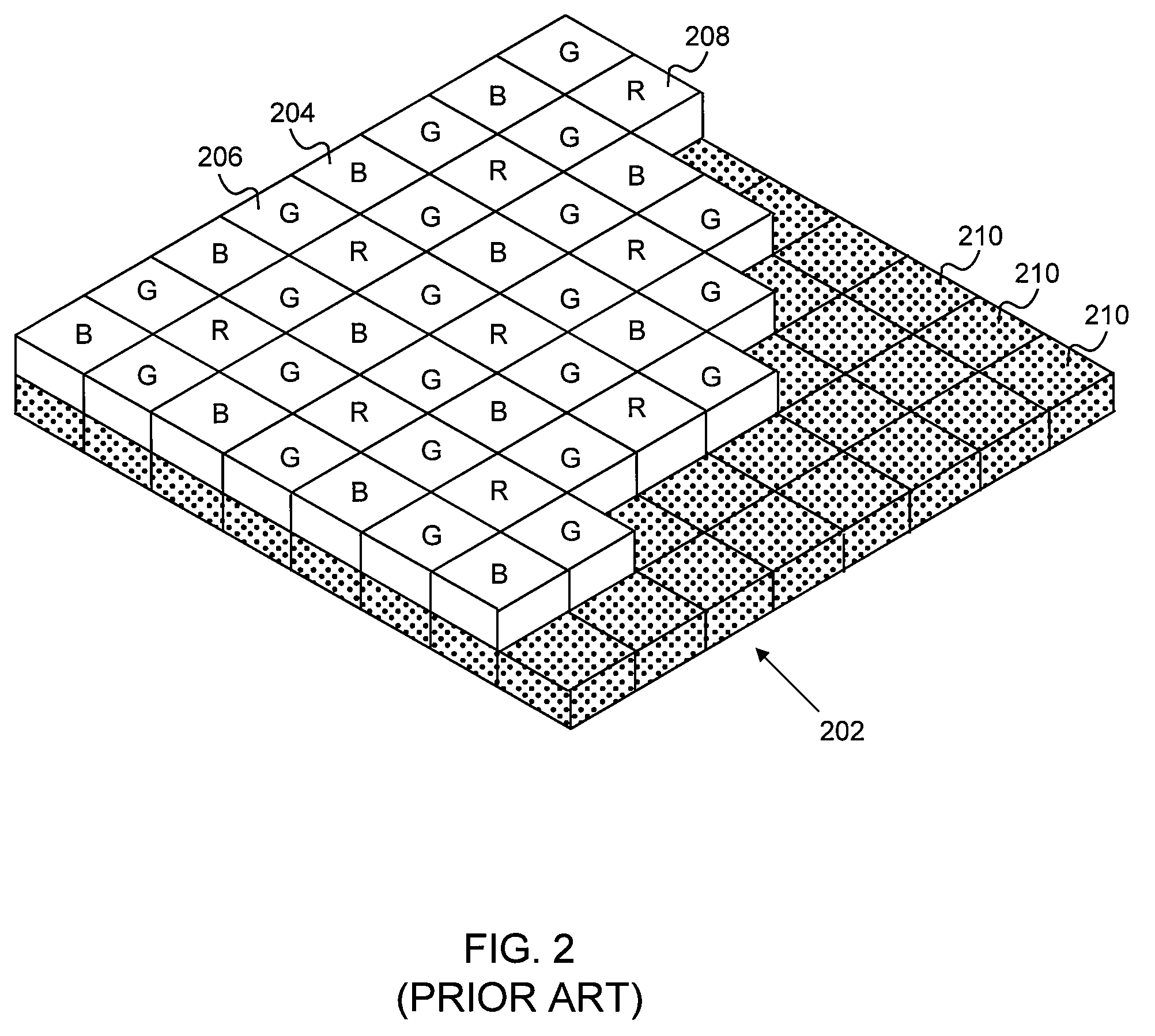
Many digital sensors are limited to having only one of the three color filters placed over each pixel location.
Thus, the sensor is only capable of determining a color value for one of the three red, green, and blue (RGB) colors at each pixel location.
One problem with conventional demosaicing approaches is that only two interpolation directions (i.e., horizontal and vertical) are used when interpolating pixel color values.
A second problem with conventional demosaicing approaches that are homogeneity-based is that homogeneity noise is introduced when the interpolation region is different than the neighborhood used to determine homogeneity.
This noise may cause the conventional demosaicing algorithm to fail to choose the best interpolation direction for a particular pixel, resulting in lower image quality.

Method used


Image

  • System and method for image demosaicing
  • System and method for image demosaicing
  • System and method for image demosaicing

Examples


Embodiment Construction

[0029]In the following description, numerous specific details are set forth to provide a more thorough understanding of the invention. However, it will be apparent to one of skill in the art that the invention may be practiced without one or more of these specific details. In other instances, well-known features have not been described in order to avoid obscuring the invention.

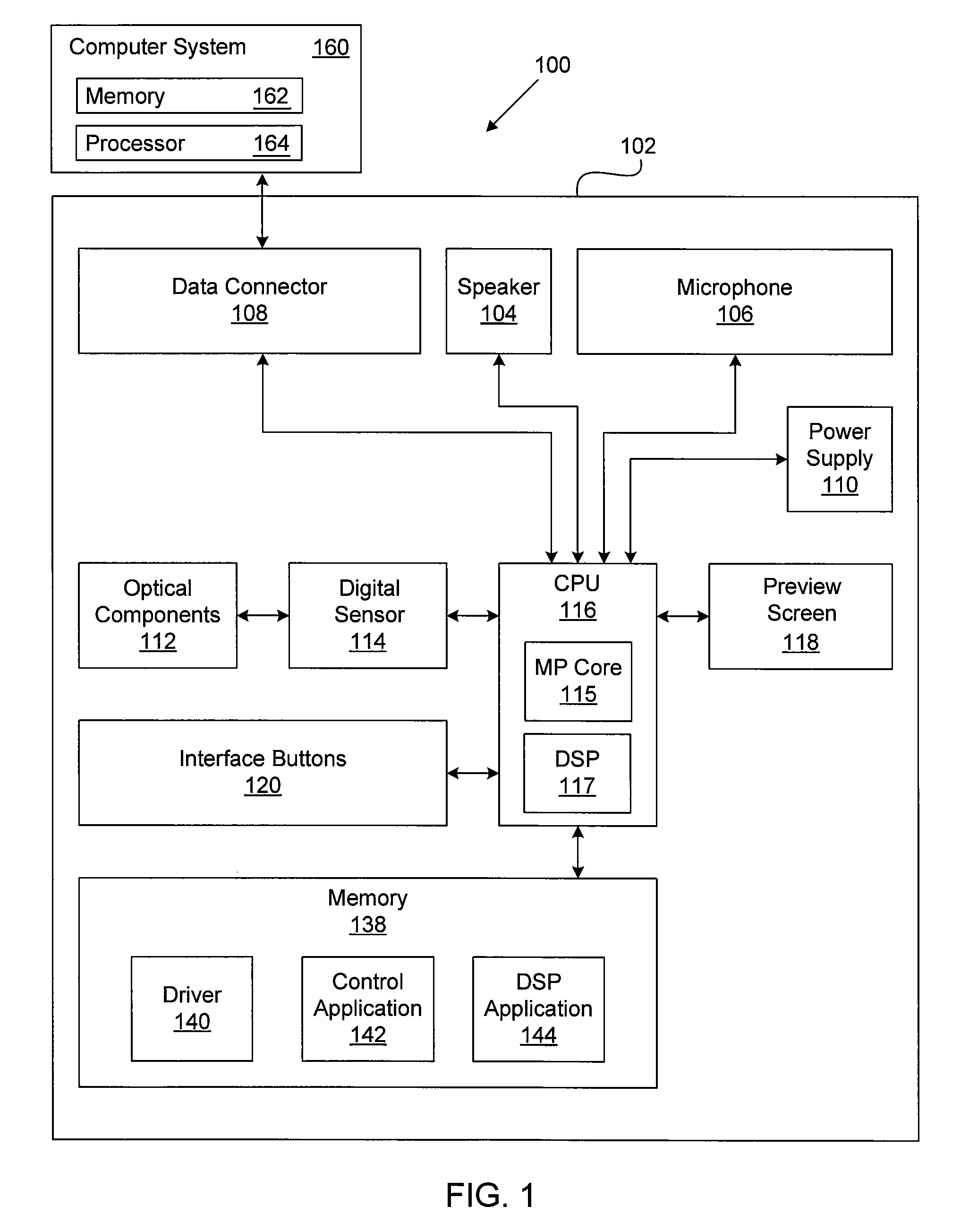
[0030]FIG. 1 is a block diagram of a system 100 configured to implement one or more aspects of the invention. As shown, the system 100 includes a digital camera 102 and a computer system 160. The digital camera 102 includes, without limitation, a data connector 108, a speaker 104, a microphone 106, a power supply 110, optical components 112, a digital image sensor 114, a central processing unit (CPU) 116, a preview screen 118, interface buttons 120, and an internal memory 138. In one embodiment, the digital camera 102 is a one-time use and / or disposable digital camera. In alternative embodiments, the digital c...


PUM


Abstract

A method for generating an interpolated output image, including generating a first interpolation array including RGB values, at least one of which is interpolated, based on a first interpolation region, and generating a first homogeneity array based on the first interpolation array including homogeneity values calculated based on a first homogeneity neighborhood having the same pixel locations as the first interpolation region. The method includes generating a second interpolation array based on a second interpolation region, and generating a second homogeneity array based on the second interpolation array and a second homogeneity neighborhood, where the second homogeneity neighborhood includes the same pixel locations as the second interpolation region. The method includes determining, for a first pixel location, that the homogeneity value in the first homogeneity array is greater than the homogeneity value in the second homogeneity array, and outputting the RGB color values in the first interpolation array.

Description

BACKGROUND OF THE INVENTION[0001]1. Field of the Invention[0002]The invention relates generally to image processing and, more specifically, to a system and method for image demosaicing.[0003]2. Description of the Related Art[0004]Digital camera technology has developed rapidly over the past decade. A broad variety of digital cameras are now available to meet the diverse needs of a wide spectrum of consumers. Digital camera technology provides a user with a convenient device to capture image data and to transfer the captured image data to a medium. The medium may be a computer-readable medium, such as a Digital Video Disc (DVD) or a computer memory, or the medium may be a physical medium, such as photographic paper.[0005]In a typical digital camera, a lens projects an image onto a digital sensor that is divided into a grid of pixels. A captured image is a recording of how much light energy is measured at each pixel location. To record color information, a red color filter, a green co...

Claims


Application Information

Patent Timeline
Patent Type & Authority Patents(United States)
IPC IPC(8): G06K9/00
CPCG06T3/4015H04N9/045H04N23/843H04N25/134
Inventor KALMAN, MARK
Owner CISCO TECH INC
Learn More