Eureka AIR delivers breakthrough ideas for toughest innovation challenges, trusted by R&D personnel around the world.

Construction equipment including rear view camera

a construction equipment and rear view technology, applied in television systems, analog and hybrid computing, computation using non-denominational number representation, etc., can solve problems such as troublesome safety driving, inconvenience for drivers when operating the changeover switch during driving, and insufficient monitoring of obstacles positioned on the ground around construction equipment, so as to enhance driving convenience and enhance driving safety

Inactive Publication Date: 2012-12-25
VOLVO CONSTR EQUIP HLDG SWEDEN AB
View PDF4 Cites 1 Cited by
  • Summary
  • Abstract
  • Description
  • Claims
  • Application Information

AI Technical Summary

Benefits of technology

[0008]One object of the present disclosure is to provide construction equipment including a rear view camera to permit a driver to view rearward traffic conditions by displaying a rear image taken by the rear view camera on a monitor installed in a cabin, thereby enhancing driving safety.
[0009]Another object of the present disclosure is to provide construction equipment including a rear view camera to permit a driver to turn off an image provided from the rear view camera on a monitor, without manipulating a changeover switch, thereby enhancing driving convenience.
[0017]With the above description, the construction equipment including the rear view camera according to a preferred embodiment of the present disclosure includes the following advantages.
[0018]The image of the rear side of the construction equipment taken by the rear view camera is displayed on the monitor provided in the cabin, thereby ensuring the driving safety.

Problems solved by technology

In this instance, since the changeover switch is placed apart from a manipulation unit for operating the equipment, the driver experiences inconvenience in operating the changeover switch during driving.
In addition, in the case where the rear view camera is installed at the rear surface of the counterweight, since the rear view camera is placed at a relatively high position, it is not sufficient to monitor obstacles positioned on the ground around the construction equipment.
As a result, the lower driving structure comes in contact with the obstacle, or is trapped in the obstacles, which makes the safety driving in trouble.
In particular, in the case where the image of the obstacle taken by the rear view camera is displayed on the monitor, it is difficult for the driver to check the actual distance between the construction equipment and the obstacle, which deteriorates practical use.

Method used


Image

  • Construction equipment including rear view camera
  • Construction equipment including rear view camera
  • Construction equipment including rear view camera

Examples


Embodiment Construction

[0024]Hereinafter, exemplary embodiments of the present disclosure will be described with reference to the accompanying drawings. The matters defined in the description, such as the detailed construction and elements, are nothing but specific details provided to assist those of ordinary skill in the art in a comprehensive understanding of the present disclosure, and thus the present disclosure is not limited thereto.

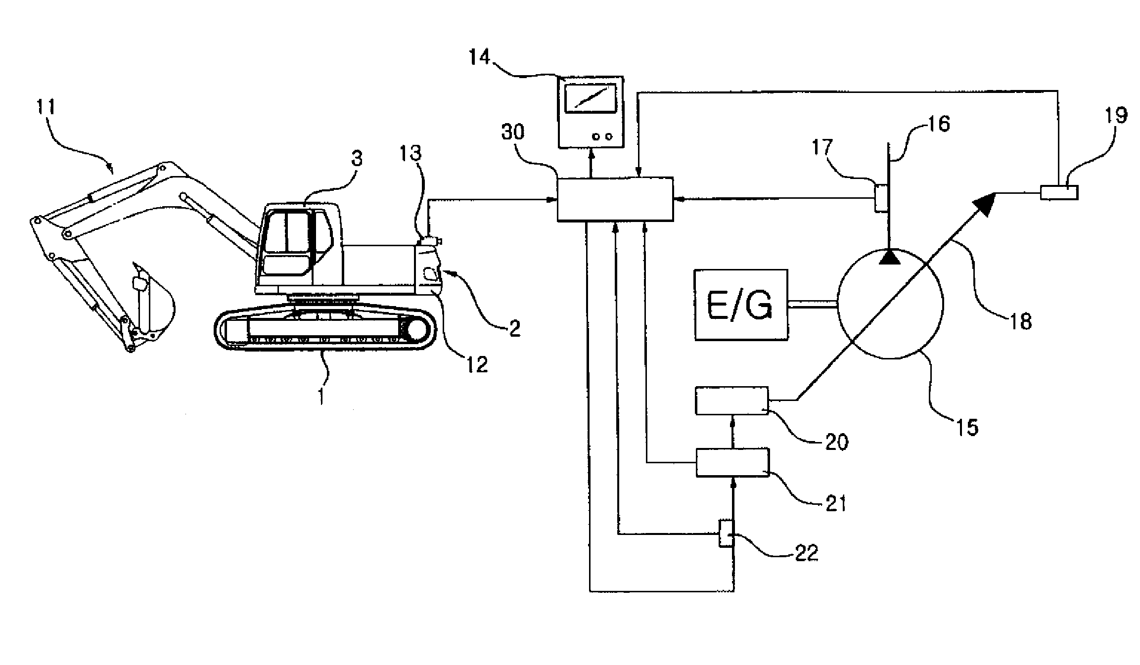
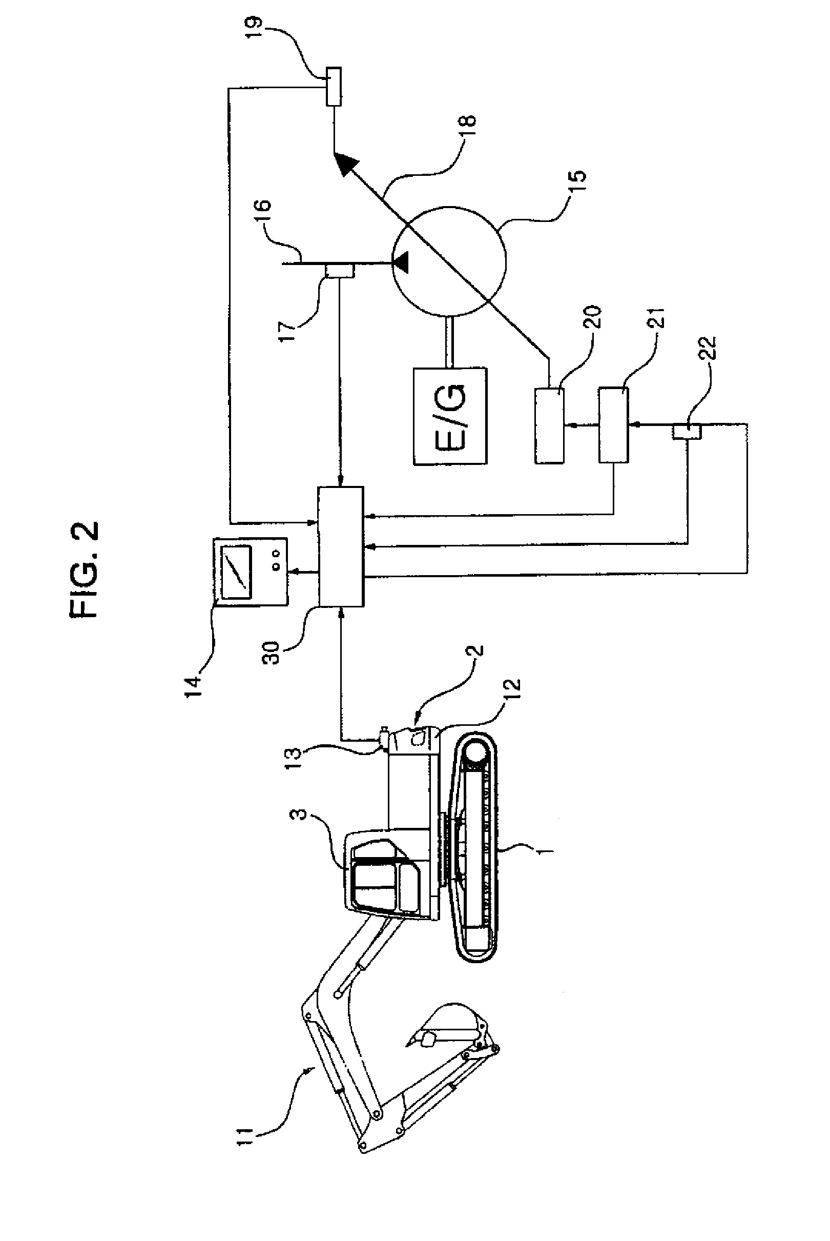
[0025]FIGS. 2 and 3 are block diagrams illustrating a construction equipment including a rear view camera and a control unit of the rear view camera according to a preferred embodiment of the present disclosure.

[0026]The construction equipment includes a variable capacity hydraulic pump (hereinafter, referred to as hydraulic pump) driven by an engine (E / G), a lower driving structure, an upper swing structure swingably mounted on the lower driving structure, a working device mounted on the upper swing structure and having a boom, an arm and a bucket respectively driven by...


PUM


Abstract

Construction equipment including a hydraulic pump driven by an engine, a lower driving structure, an upper swing structure swingably mounted on the lower driving structure, a working device mounted on the upper swing structure and having a boom, an arm, and a bucket respectively driven by a hydraulic cylinder is disclosed. The construction equipment comprises a rear view camera to permit a driver to view rearward traffic conditions.

Description

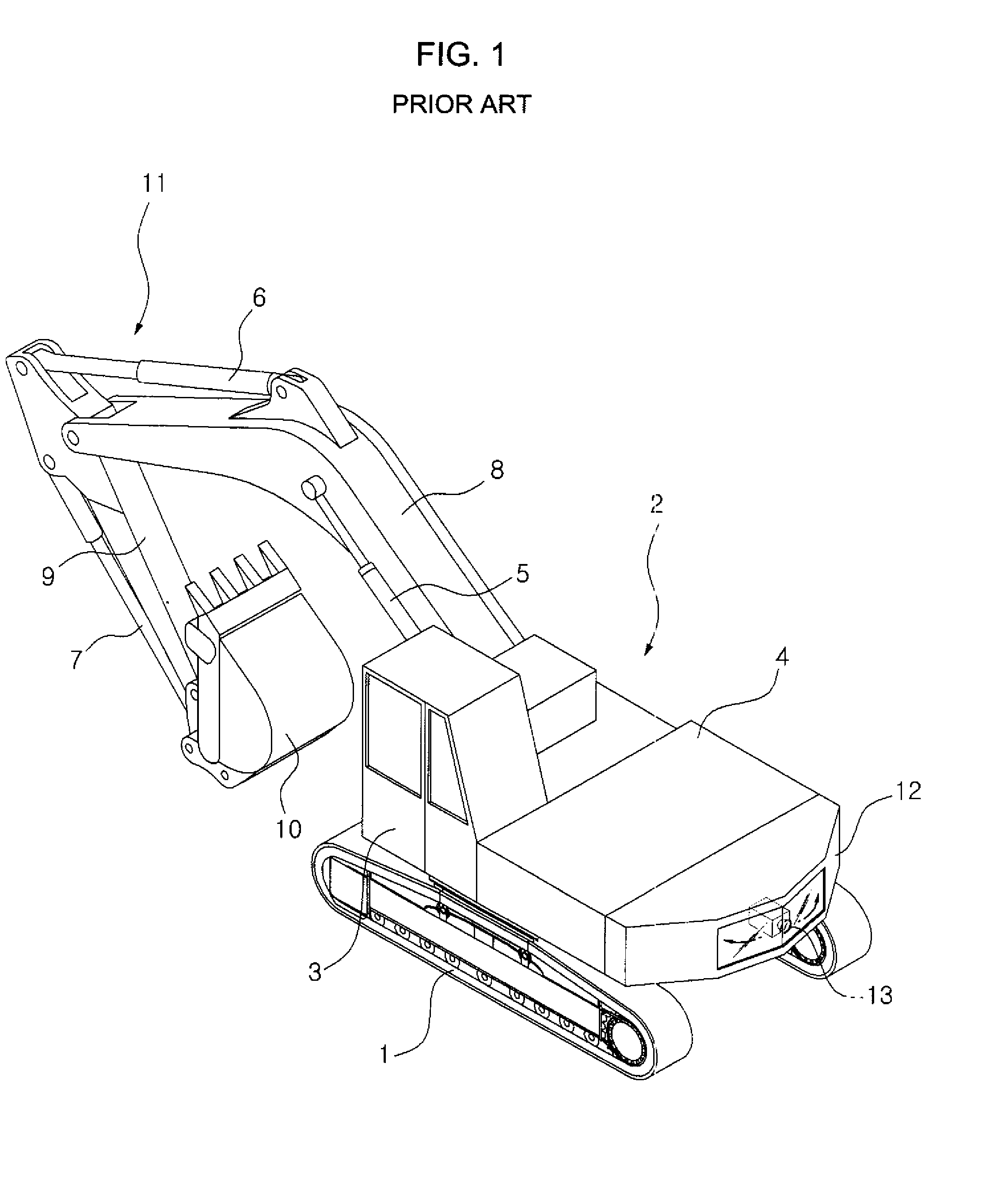
CROSS-REFERENCE TO RELATED APPLICATION[0001]This application is based on and claims priority to Korean Patent Application No. 10-2009-11523, filed on Feb. 12, 2009, in the Korean Intellectual Property Office, the disclosure of which is incorporated herein in its entirety by reference.FIELD OF THE DISCLOSURE[0002]The present disclosure relates to a construction equipment, and more particularly, to construction equipment including a rear view camera to permit a driver to view rearward traffic conditions.BACKGROUND OF THE DISCLOSURE[0003]FIG. 1 shows a hydraulic excavator including a rear view camera according to a related art. The excavator includes a lower driving structure 1; an upper swing structure 2 swingably mounted on the lower driving structure 1; a cabin 3 and an engine 4 mounted on the upper swing structure 2; a working device 11 mounted on the upper swing structure 2 and having a boom 8 driven by a boom cylinder 5, an arm 9 driven by an arm cylinder 6, and a bucket 10 drive...

Claims


Application Information

Patent Timeline
Patent Type & Authority Patents(United States)
IPC IPC(8): G06F7/70
CPCB60R1/00E02F9/26B60R2300/70E02F9/0858E02F9/261B60R1/08E02F9/24H04N7/18
Inventor LEE, CHUN HAN
Owner VOLVO CONSTR EQUIP HLDG SWEDEN AB
Why Eureka
Eureka Blog
Learn More