Modular support, assemblies, methods and systems

a module and assembly technology, applied in the field of modules, can solve the problems of affecting the assembly, affecting the assembly, and unable to detect the fault, so as to reduce the number of parts and cost, and the object is organized better

Inactive Publication Date: 2013-01-01
THE GATES CORP
View PDF22 Cites 61 Cited by
  • Summary
  • Abstract
  • Description
  • Claims
  • Application Information

AI Technical Summary

Benefits of technology

[0008]The present invention is directed to systems and methods which provide secure, variable, modular support for multiple objects. An example of a support system that exhibits superior organization of objects can be seen in embodiments of the present invention. The present modular support assembly comprises a system of bracketry in the form of modules that can be put together in many configurations and used in a multitude of applications. In particular, the present modular support assemblies, methods and systems advantageously provide a flexibility to capture individual conduits and then lock multiple conduits together in various configurations, as needs may dictate. Although embodiments of the present modular support assembly can be used to support and transport many types of objects, particularly elongated objects, the modular support assembly is preferably used for the housing, transport, and support of elongated objects having a generally cylindrical cross-section, such as individual and bundled fluid conduits, including hydraulic hoses, tubes, and pipes. The use of a modular configuration results in reduced part count and cost via standardization, and allows fluid conduits to be pre-bundled at the supplier level prior to equipment installation. The present modular support assembly may therefore be an attractive stock item for fluid conduit distributors.
[0009]While other modular shapes are contemplated, parallelepiped, rectangular, triangular, or other-shaped cross-sections, various embodiments of the present invention have modules of a generally block-type shape. The present modular support assembly comprises an assembly of these interchangeable modules. The modules can comprise a variety of sizes and can be placed around the fluid conduits either before or after the conduits have been bundled or placed. Each individual module comprises an aperture that receives one conduit. The ability to place the module around (or onto) the conduit before or after installation of the conduit is made possible by sliding the entire module over / onto the conduit or by providing modules that comprise two, preferably interchangeable module portions or halves, each portion comprising approximately one half of the module, wherein the portions are slidably removable from one another along a longitudinal plane of the conduit retained therein. Other embodiments of the present invention may provide modules having two parts that differ vastly in size. Each module can be removed from the assembly in its entirety or in part. When one module portion is removed from the other module portion, a “pick and place” method of inserting the conduit into the module's aperture can be employed. This is a very beneficial feature of the design because it allows for conduit accessibility and maneuverability in tight spaces. An important advantage of the present embodiment is that a module can be moved to different parts of the assembly, including beside or underneath another module. The ability to move the modules from beside one another to below / above one another provides versatility in support. For example, a flipped module could act as a spacer during emergency repair. A further advantage of each module receiving one conduit is that removal of one object can be achieved while maintaining the overall structure of a modular support assembly. The present invention provides a non-disruptive, easy to implement method of storing, transporting, and separating objects, including hydraulic fluid conduits and becomes very beneficial when long lengths of pipe or tube are transported or installed together.
[0010]In various embodiments, the modules are cube-like in structure, having six sides. The dimensions and shape of the modules can vary depending upon the intended use of the assembly. For example, modules having a thickness that is greater than their width and height dimensions may be well suited for large diameter, heavy conduits. In cube-like module embodiments, similarly and differently-sized modules are engaged with one another by a system of slidable, inter-locking engagement portions, such as slide and groove fasteners or joints, disposed along the periphery of the modules. The slide and groove joints may include interlocking fan-shaped tails and sockets as seen in sliding dovetail joints. Each block has, on at least four of its sides, including the top, bottom, left, and right sides, alternating tails and sockets. Thusly, depending on the number of tails and sockets per side, where there is a tail on a left side of the module, at the same location on a module's opposing (right) side there will be a socket. Similarly, where there is a tail on the bottom side of the module, at the same location on the module's opposing (top) side there will be a socket. The size, placement, and design of the engagement portions are preferably the same on each module, regardless of the size of the module itself. This similarity in the size of the tail and socket facilitates engagement of any size of module with any other size of module. Because of this design of the module, large and small modules can be removed from the modular support assembly by removing module portions or whole modules at will. This allows for spontaneous creation of support along any portion of the fluid conduit, post-installation. An example of when this feature might be desirable is when a large outside diameter (OD) conduit such as an oil pipe needs repair and this large OD pipe is bundled with other, possibly smaller fluid conduits.

Problems solved by technology

The support apparatus usually includes supportive blocks or clips that may be welded to the conduits in an expensive process that requires post-finishing operations, and these blocks may have several unique, difficult to install parts that are made specifically for the application.
One disadvantage of this system is that if the arm is not properly locked into place, there exists no tell-tale sign that anything is amiss.
A disadvantage of Campbell '802 and many other currently available hose and pipe supports is that each support portion or block typically comprises a multitude of apertures to receive multiple pipes.
In most cases, this requires removing the inhibiting surrounding row(s), disrupting the entire assembly, and increasing labor cost.
Disassembling the entire assembly becomes impossible in areas having low clearances such as certain equipment, mechanical rooms and other storage locations, trucks, trailers, and other transport vehicles.
Usually, these separate means of attachment comprise bolts, which negatively impact the cost of materials and installation.
In still other support systems, there is no means at all for securing one support block to another.
An S-bend installation results in excessive hose movement and diminished service life.

Method used


Image

  • Modular support, assemblies, methods and systems
  • Modular support, assemblies, methods and systems
  • Modular support, assemblies, methods and systems

Examples


embodiment 100

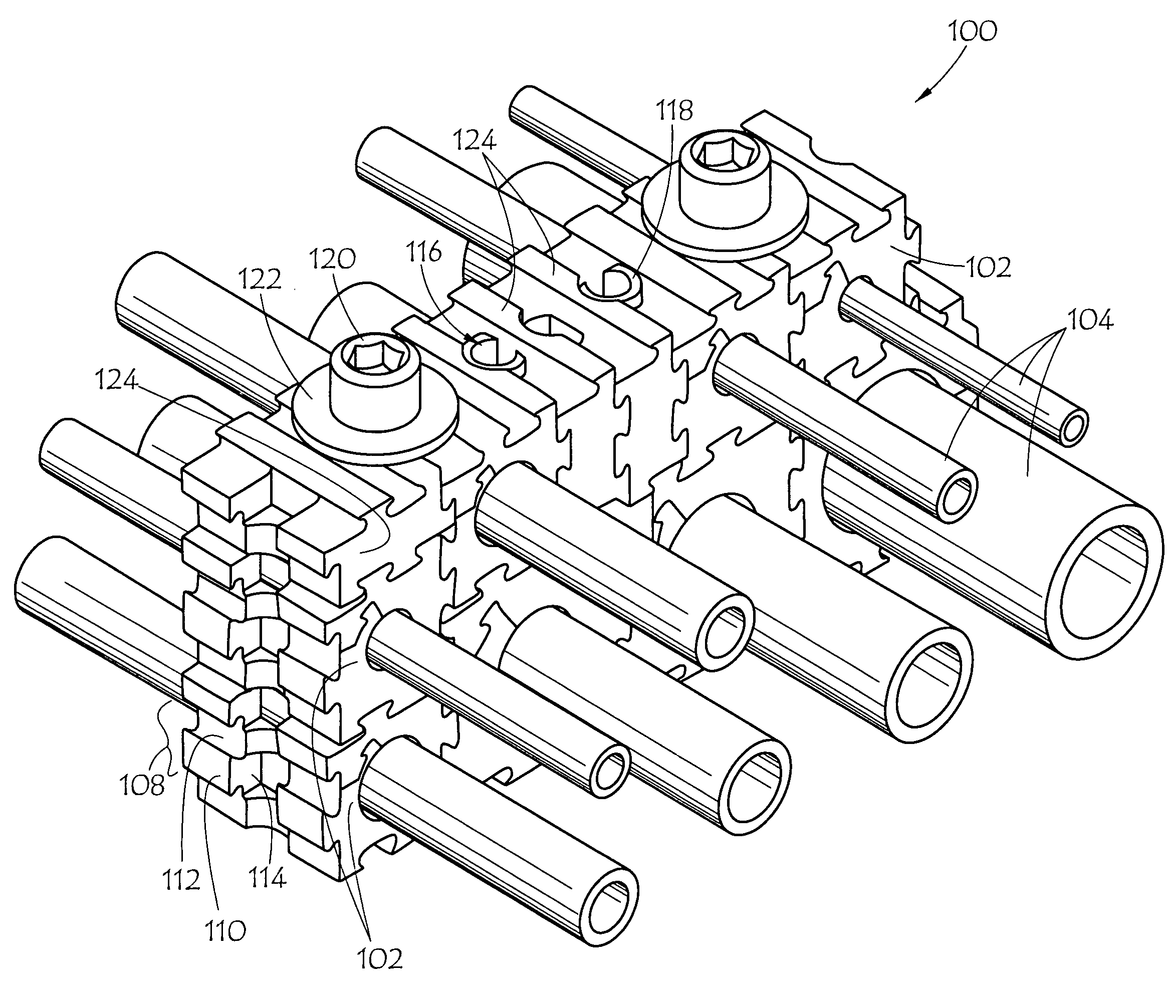
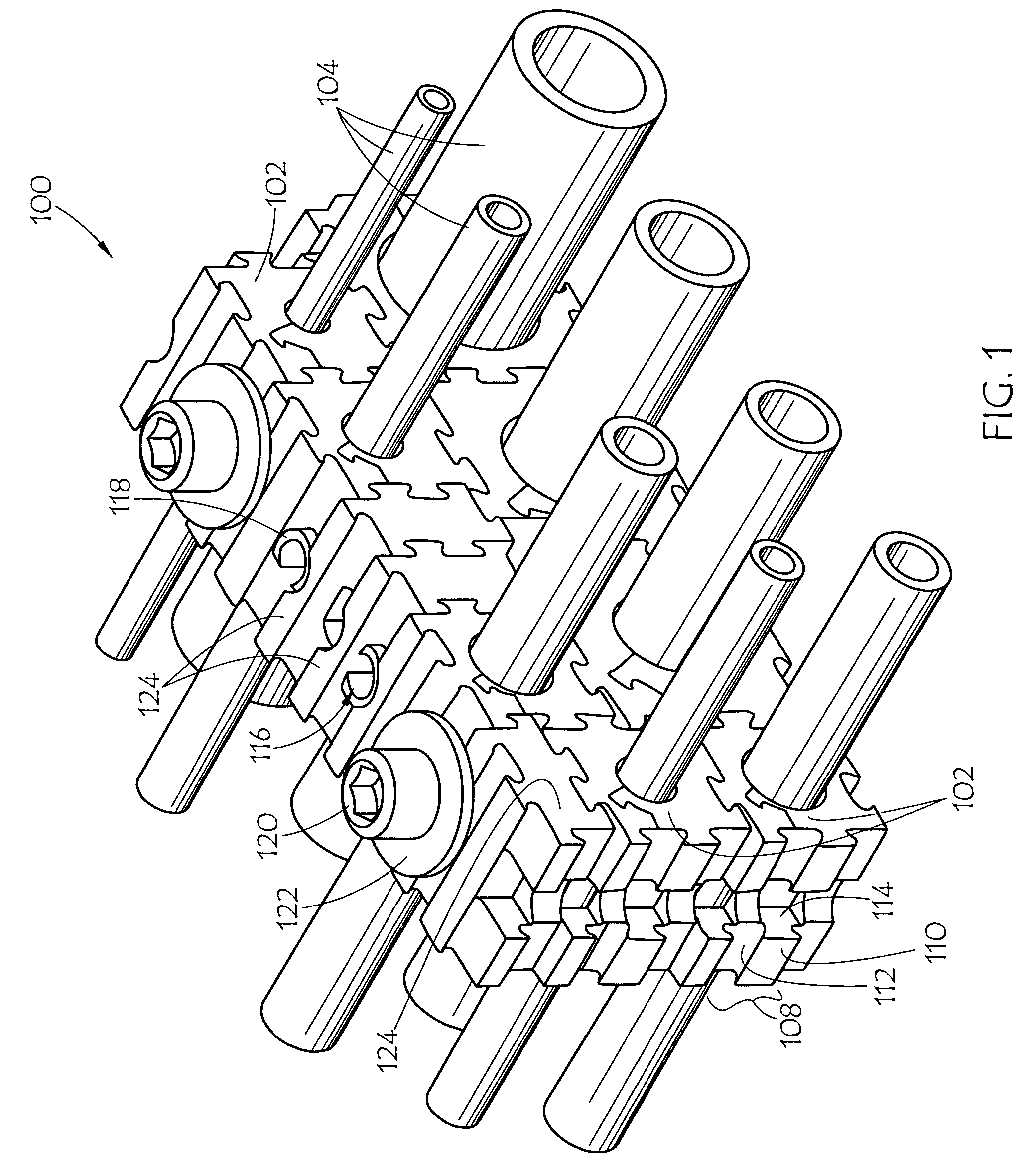
[0031]Referring to FIG. 1, embodiment 100 of the present invention is shown supporting a varying number and sizes of elongated, generally cylindrical objects 104. In various embodiments of the present invention, the cylindrical objects may comprise fluid conduits. However, it should be understood that the present assemblies can receive, support, transport, and store objects having virtually any cross section, including square, elliptical, oblong, or oval-shaped cross sections as well as objects of virtually any type or size including airplane fuselages or portions thereof, machinery parts, construction components, medical, sports, or other equipment, large oil pipe lines, transport vessels, etc.

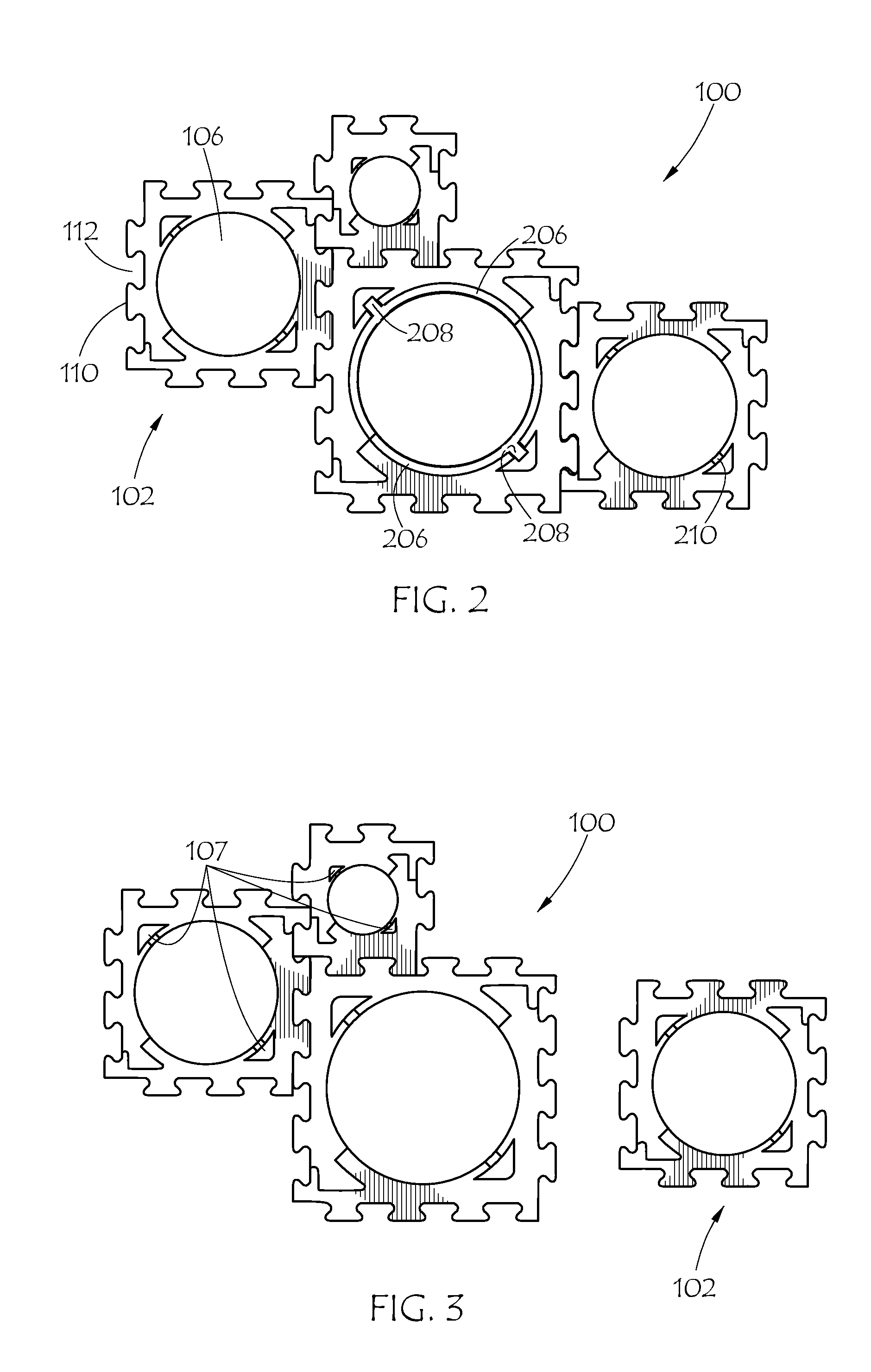
[0032]Turning to FIGS. 2-4, in various embodiments of the present invention, the fluid conduits may comprise hydraulic hose, pipe and tube. A bundle of various cross sections of conduit is supported by modular support assembly 100 comprised of modules 102. Modules 102 may comprise varying siz...

embodiment 602

[0050]Module embodiment 602, may also make use of an insert, such as insert 206, discussed above. Preferably the use of such an insert allows a limited number of modules sizes to be used with a greater number of conduit sizes. Reliefs 607 also facilitate providing a more constant thickness to module portions 603. Reliefs 607 preferably each define a slot to receive an insert tab, such as in a snap-fit manner.

[0051]Hence, in module 602, module portions 603 have a relatively constant thickness throughout, which should facilitate molding of portions 603, as molded parts will preferably cool more evenly and will not be as likely to “'sink” in thick areas.

[0052]As mentioned previously, historically, other support mechanisms require the removal of all inhibiting support blocks in order to access a conduit housed by a surrounded support block. An advantage provided by the modular support assembly 100 is that simple and easy removal of a conduit 104 can be achieved, even for those conduits ...


PUM


Abstract

A modular support assembly receives and / or stores elongated objects that may be primarily cylindrical in shape, such as fluid conduits including hydraulic tube, pipe and hose. The modular support assembly includes a plurality of interchangeable modules of differing or similar sizes to create an adjustable assembly whose overall shape and number of modules can change depending upon the intended use of the assembly. The modules comprise sliding engagement portions that are disposed along a periphery of the modules and allow interengageable attachment to other modules. The modules also comprise apertures that can vary in size to accommodate various sizes of objects. The modules can be disassembled by sliding module portion halves apart, facilitating easy assemblage of the modules either before or after the objects retained therein have been positioned, and subsequent removal of individual objects from the assemblage.

Description

CROSS-REFERENCE TO RELATED APPLICATION[0001]This application claims the benefit of U.S. Provisional Application No. 61 / 068,500, entitled Modular Support Assembly, Methods and Systems, filed Mar. 7, 2008, which is incorporated herein by reference.BACKGROUND OF THE INVENTION[0002]1. Field of the Invention[0003]This invention relates generally to support systems for objects, more particularly to modular assemblies for supporting elongated objects that may be primarily cylindrical in shape, and specifically to assemblies of interchangeable modules of differing or similar sizes to create adjustable assemblies whose overall shape and number of modules can vary depending upon the intended use of an assembly.[0004]2. Description of the Prior Art[0005]Supports for generally cylindrical objects, including fluid conduits such as hydraulic pipe, tube, and hose, are known. Such supports typically include an apparatus that securely receives and stores bundles of pipes, tubes and / or hoses while ma...

Claims


Application Information

Patent Timeline
Patent Type & Authority Patents(United States)
IPC IPC(8): F16M13/00
CPCF16L3/222
Inventor GILBREATH, DONALD R.
Owner THE GATES CORP
Why Eureka
Try Eureka