Lens with controlled backlight management

a backlight management and led light technology, applied in the field of led light fixtures, can solve the problems of less than desirable lighting patterns, less than fully efficient illumination patterns, and less than desirable led-emitted light, and achieve the effect of efficient use of led ligh

Active Publication Date: 2013-01-08
IDEAL IND LIGHTING LLC
View PDF176 Cites 39 Cited by
  • Summary
  • Abstract
  • Description
  • Claims
  • Application Information

AI Technical Summary

Benefits of technology

[0010]Another object of the invention is to provide an LED lens with improved control of the direction of light exiting the lens.
[0012]This invention is a lens with improved efficiency of distribution of light predominantly toward a preferential side from a light emitter such as an LED package having an emitter axis and defining an emitter plane. It is preferred that the light emitter is the LED package which is free of a surrounding reflective surface. Such improved efficiency of light output from the light emitter is achieved with the inventive lens which is specifically designed for refraction and useful output of light emitted in directions opposite to the desired illumination direction. The inventive lens directs the great majority of light from the emitter in the preferential-side direction, including light emitted at angles which previously resulted in the loss of such light. Such efficiency of light use is provided without use of separate reflectors—that is, on a lens-only basis.
[0017]Referring to such elliptical cross-sections, it is preferred that each cross-section be symmetrical about its midpoint, and that it be centered on the plane extending from the center of the non-preferential side to the center of the preferential side. In the preferred embodiments in which the elliptical cross-section face the ellipse major axis, the distances from each elliptical cross-section to the emitter axis increase at positions away from such s these cross-sections extend away from the plane extending from the center of the non-preferential side to the center of the preferential side. Such configuration allows wide-angle distribution of emitter light to the preferential side. In other embodiments, in which the cross-sections of the inner-surface back sector and the primary back surface have shorter radii of curvature, narrower and farther patterns of light distribution toward the preferential side are achieved.
[0029]As noted earlier, efficient use of LED light is important, particularly in applications involving illumination toward a preferential side. The inventive lens, in its preferred embodiments, is capable of directing 10% more of the total emitted light toward the preferential side than with prior lenses designed for preferential-side distribution. In such preferred embodiments, the inventive lens effectively utilizes as much as 90% of the emitter light for achieving useful illumination.

Problems solved by technology

However, such lenses have tended to fall short of the most desirable performance in that some LED-emitted light is lost.
Typically, some of the light from LEDs is emitted at angles that cause LED-lighting fixtures to provide less than desirable and less than fully efficient illumination patterns.
Even though these configurations were deemed necessary to achieve desired illumination patterns and to prevent so-called lighting “trespass,” they tended to result in lost light and decreased efficiency of LED illuminators.
This has made it very difficult to control refraction of such light.
As a result, only a portion of light being refracted is refracted in a desired direction, while the reminder exits the lens with very little control.

Method used


Image

  • Lens with controlled backlight management
  • Lens with controlled backlight management
  • Lens with controlled backlight management

Examples


Embodiment Construction

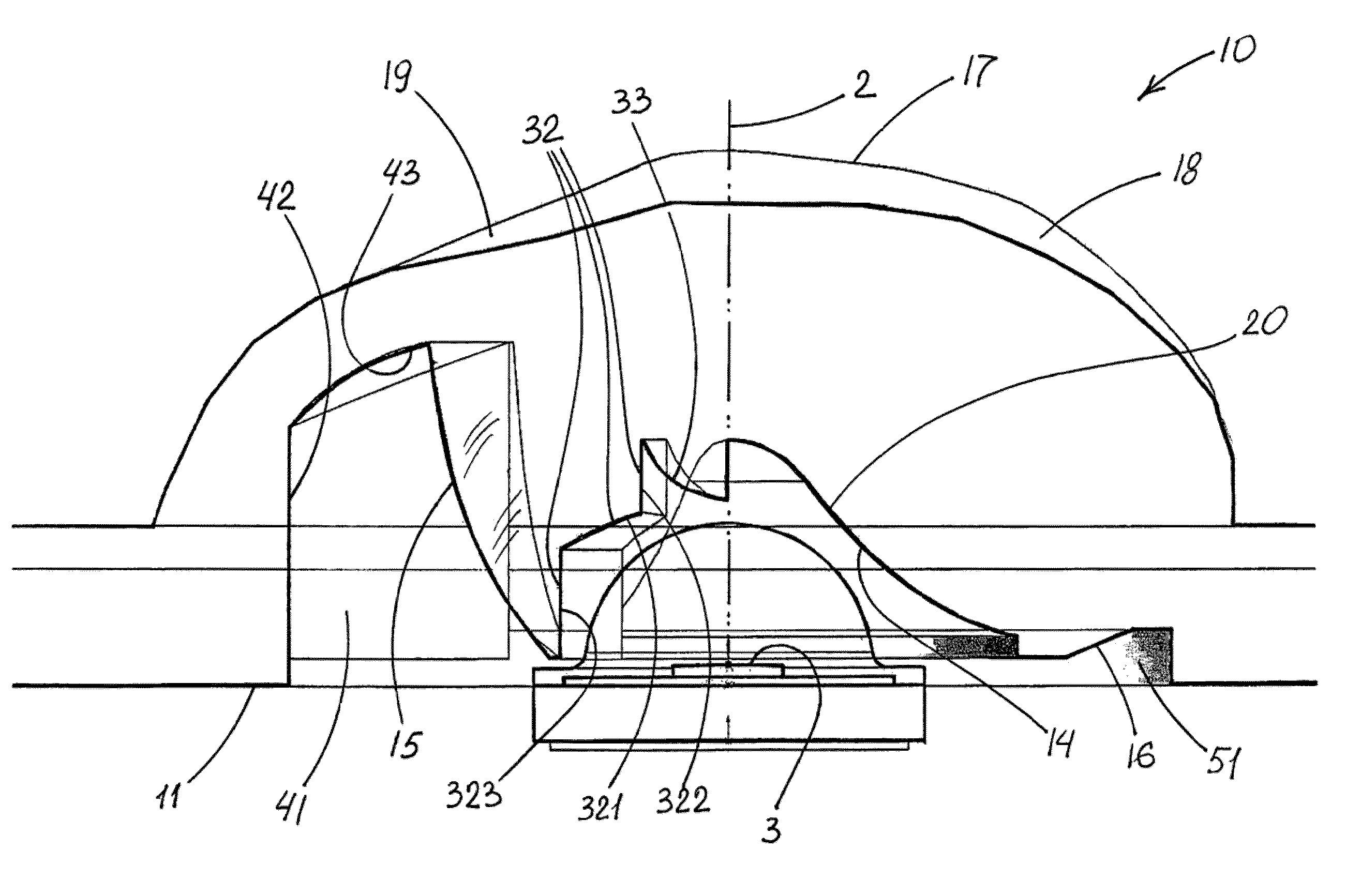
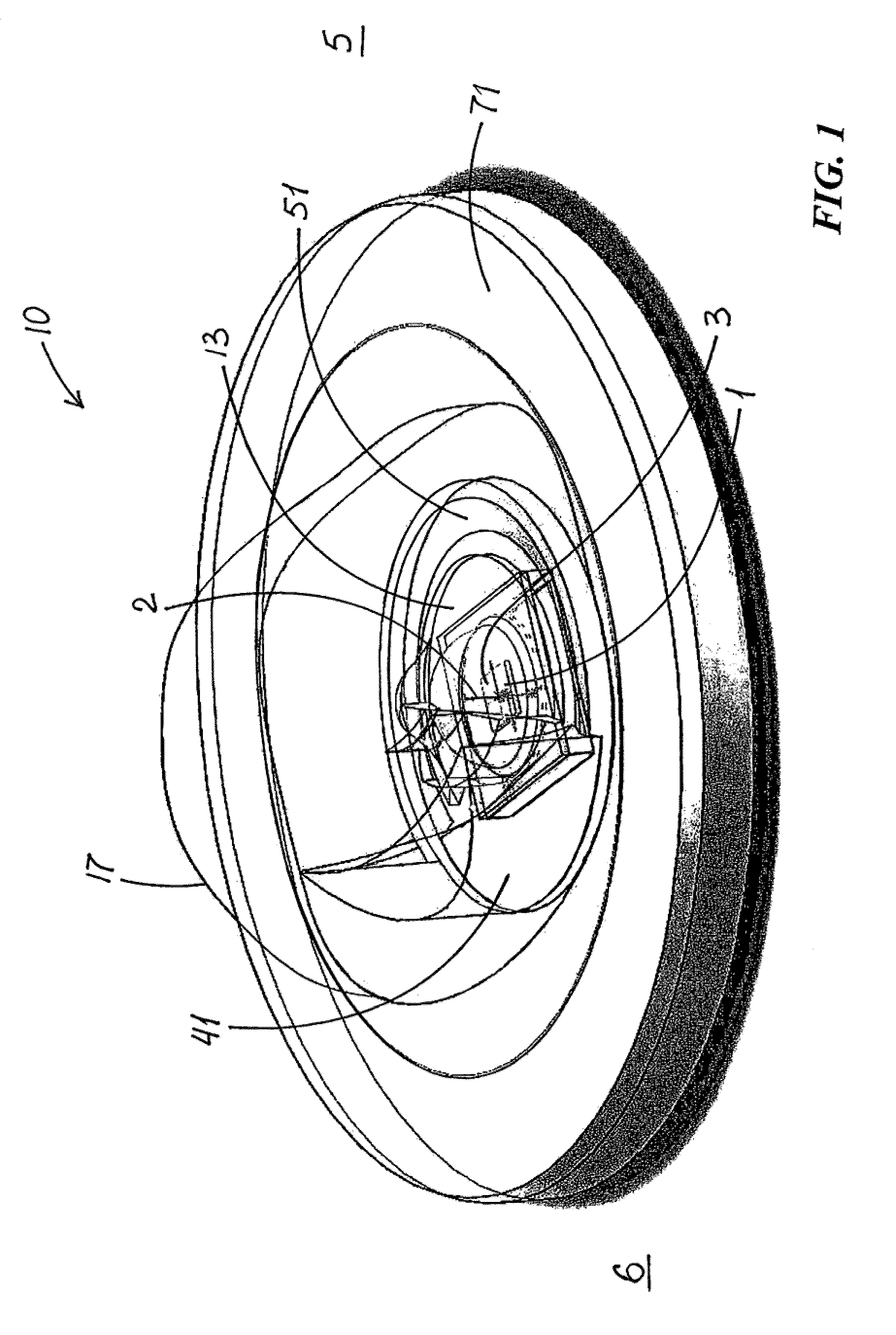
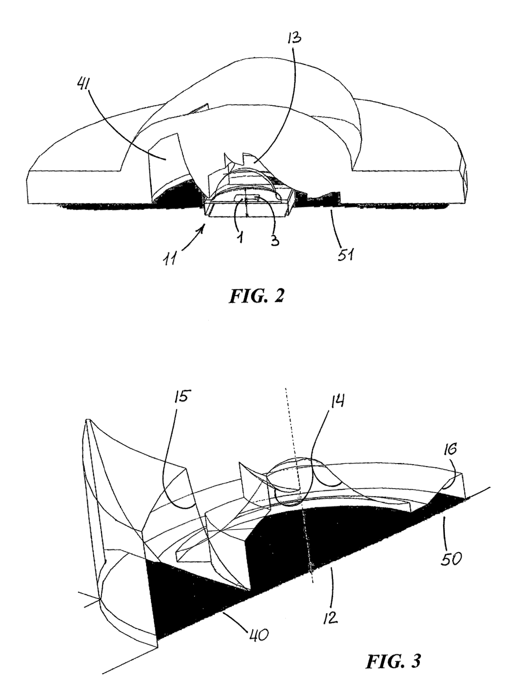
[0048]FIGS. 1-20 illustrate lens 10 which is a preferred embodiment of the invention. Lens 10 is for distribution of light predominantly toward a preferential side 5 from a light emitter 1 which has an emitter axis 2 and defines an emitter plane 3. As seen at least in FIGS. 1 and 2, light emitter 1 is an LED package which is free of a surrounding reflective surface.

[0049]Lens 10 has an emitter-adjacent base end 11 which forms an emitter-receiving opening 12 to an emitter-surrounding cavity 13 defined by an inner surface 14. Cavity 13 defines a space between emitter 1 and an inner-cavity surface 14 such that emitter light goes through air to enter lens material at inner-cavity surface 14. Because air and the lens material, which may be acrylic or other suitable material, have different refraction indexes, this results in bending of the light at inner-cavity surface 14.

[0050]Inner surface 14 includes a front sector 20 centered on preferential side 5 and a back sector 30 centered on th...


PUM


Abstract

A lens for distribution of light predominantly toward a preferential side from a light emitter having an emitter axis and defining an emitter plane. The lens has an emitter-adjacent base end forming an emitter-receiving opening to an emitter-surrounding cavity defined by an inner surface which includes a front sector centered on the preferential side and a back sector centered on the non-preferential side radially opposite the preferential side. The front and back sectors differ in their respective configurations for refracting light from the emitter. The lens further includes an primary back surface positioned to receive light from at least a portion of the inner-surface back sector and configured for total internal reflection (TIR) thereof. The inner-surface back sector and the primary back surface extend along substantially elliptical cross-sections in planes substantially parallel to the emitter plane. The emitter-adjacent base end forms a back opening to a back cavity substantially centered on the non-preferential side and partially bounded by the primary back surface.

Description

RELATED APPLICATIONS[0001]This application is a continuation-in-part of currently pending U.S. application Ser. No. 12 / 173,721, filed on Jul. 15, 2008, which is based in part on U.S. Provisional Application Ser. No. 61 / 055,958, filed May 23, 2008.FIELD OF THE INVENTION[0002]This invention relates to lighting fixtures and, more particularly, to LED lightning fixtures for various common illumination purposes. Still more specifically, this invention relates to the field of lensing for desired LED light distribution in LED lighting fixtures.BACKGROUND OF THE INVENTION[0003]In recent years, the use of light-emitting diodes (LEDs) for various common lighting purposes has increased, and this trend has accelerated as advances have been made in LEDs and in LED-array bearing devices, referred to as “LED modules.” Indeed, lighting needs which have primarily been served by fixtures using high-intensity discharge (HID) lamps, halogen lamps, compact florescent light and other light sources are no...

Claims


Application Information

Patent Timeline
Patent Type & Authority Patents(United States)
IPC IPC(8): F21V5/00F21V3/00
CPCF21V5/008F21V5/04F21V7/0091F21V13/02F21V13/04G02B19/0028G02B19/0061F21Y2105/001F21Y2101/02F21V5/08F21Y2105/10F21Y2115/10
Inventor WILCOX, KURT S.STROM, CHRISTOPHER
Owner IDEAL IND LIGHTING LLC
Why Eureka
Try Eureka