Thin illumination system

a thin, illumination system technology, applied in fixed installations, lighting and heating apparatuses, instruments, etc., can solve the problems of reducing illumination efficiency, reducing and reducing the mechanical bulkiness of fixtures. , to achieve the effect of reducing off-angle glare and not compromising the sharpness of angular cuto

Active Publication Date: 2013-01-08
SNAPTRACK +1
View PDF355 Cites 88 Cited by
  • Summary
  • Abstract
  • Description
  • Claims
  • Application Information

AI Technical Summary

Benefits of technology

[0018]It is, therefore, an object of the invention to provide a compact and slim-profile means of overhead LED illumination for commercial lighting applications having a prescribed degree of angular collimation in each of its two orthogonal output meridians and a square or rectangular far field illumination pattern.
[0019]It is another object of the invention to provide a compact and slim-profile means of overhead LED illumination having its degree of angular collimation modified in each of its two orthogonal output meridians by angle-spreading located in its output aperture that maintain the illumination systems rectangular far field illumination patterns.
[0030]It is still another object of the invention to apply geometrically shaped portions of lenticular filmstrips to the input edge of light guiding plates for the purpose of widening the angle extent only in a local region of an illumination system as a means of improving near field brightness uniformity.
[0033]It is yet an additional object of the invention to provide a thin-profile illumination system whose aperture brightness has been moderated by spreading light over an enlarged area, while doing so without compromise in the sharpness of angular cutoff displayed by the illuminating beams that are produced.
[0034]It is a further object of the invention to provide a thin-profile illumination system whose aperture brightness has been moderated by spreading light over an enlarged area, while doing so without compromise in the square-ness or rectangularity of the field patterns that are produced.
[0035]It is yet a further object of the invention to provide a thin-profile illumination system whose illumination remains largely within fixed square or rectangular angular beams as a means of reducing off-angle glare visible from below.

Problems solved by technology

Even though a given lighting application may require illumination held predominately to a limited geometric area (e.g. table top or work area), nearby viewers still receive unwanted glare when looking upwards at the fixture's physical aperture.
While some conventional fixtures have been designed for limited-angle spotlighting purposes, they typically achieve net illumination efficiencies far lower than desired from a modern energy conservation perspective.
Some light, is wasted by misdirection outside the area of interest, and other light, by the inefficiency the deliberate physical baffling added to block glare, which also adds significantly to the fixture's mechanical bulkiness.
While modest gains have been made in luminaire efficiency, uniformity of illumination, and glare reduction, to mention a few, the lighting fixtures themselves have still remained as bulky and imposing as ever.
The net weight of conventional lighting fixtures is too heavy for most standard commercial ceiling frameworks without costly and cumbersome mechanical reinforcements.
Conventional recessed lighting fixtures are also quite thick, which adds to the overhead plenum space required above the decorative ceiling to accommodate them, thereby reducing the effective ceiling height.
Ceiling height reduction is particularly an issue in high-rise buildings where ceiling height is already limited by the building's structural boundary conditions.
While this trend promises still greater lighting fixture advantages over time, early developments have yet to realize the full potential.
Light emitted by LEDs is created in very small geometric regions, and as a result, the associated brightness (i.e., lumens per square meter per solid angle in steradians) can be extremely hazardous to human view without additional packaging structures added to block, restrict or diffuse direct lines of view.
While this approach prevents accidental view of the LED's directly, the associated fixtures are as bulky as conventional ones.
While this approach moderates aperture brightness in floodlighting applications, it does so at the expense of the fixture's thickness, and while also increasing the fixture's propensity for off-angle glare.
Looking at a bare LED emitter, even one combined with a reflector or a lens, is a quite unpleasant experience, typified by temporary blindness and a remnant image lasting minutes or longer.
As welcome as this possible LED lighting approach might be to commercial lighting use, the resulting fixture or luminaire is still a relatively thick and obtrusive one, veiling glare from its naturally wide angle emission remains an open issue, and beaming its output glow to limited task areas, is not provided.
And while thinner than conventional light bulb based lighting fixture, LED backlights are still too thick to be conveniently embedded within the body of typical building materials such as ceiling tiles and wall board.

Method used


Image

  • Thin illumination system
  • Thin illumination system
  • Thin illumination system

Examples


Embodiment Construction

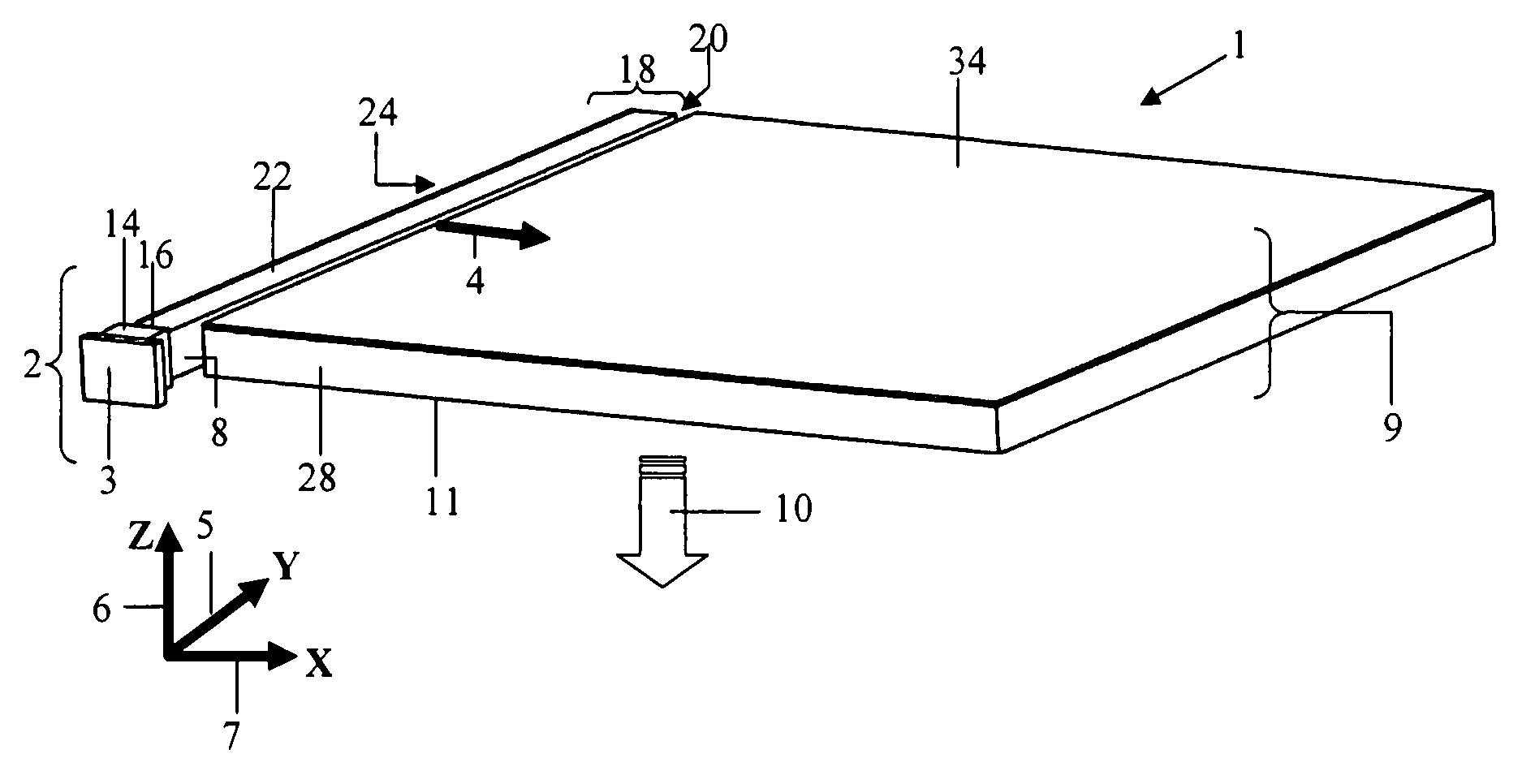
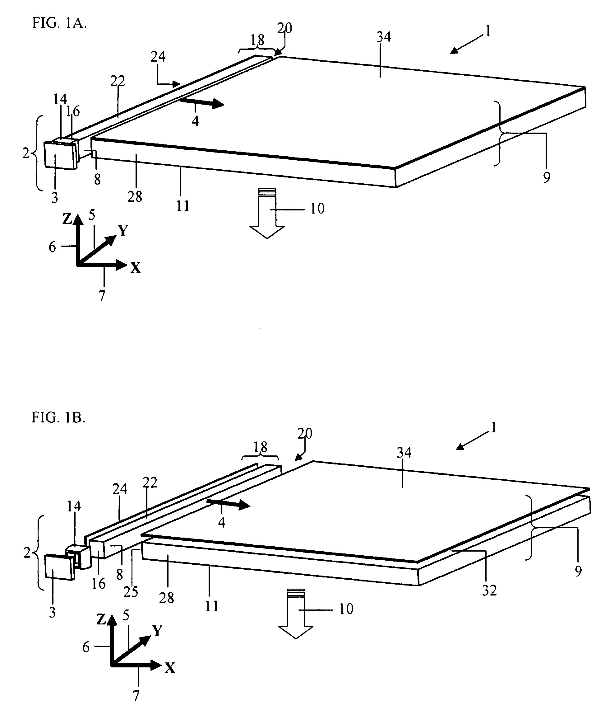
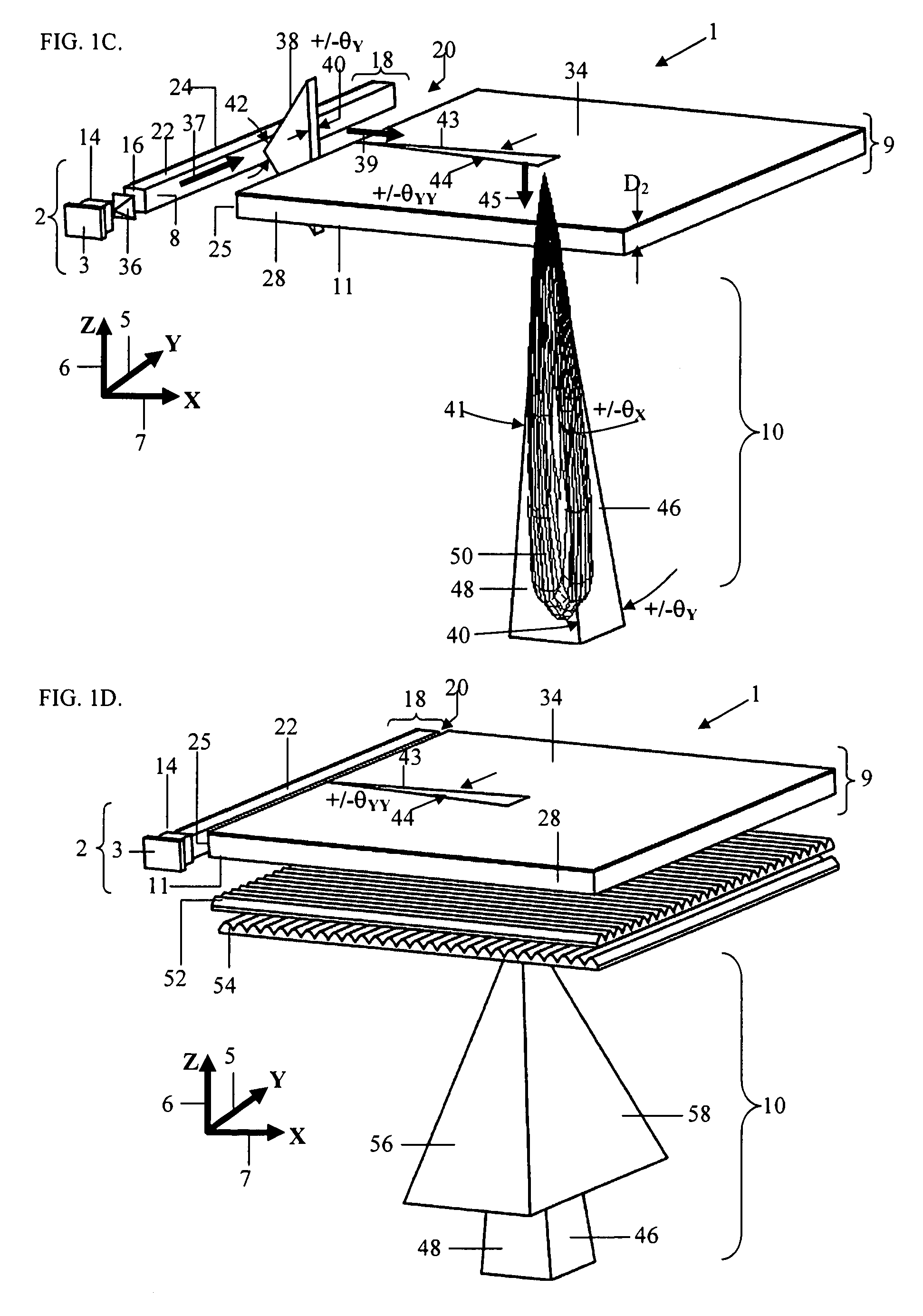
[0170]An optical system 1 constructed in accordance with one principal form of the thin-profile illumination invention is indicated generally in the schematic perspective shown in FIG. 1A and in the exploded perspective shown in FIG. 1B. This form of the present invention collects the light from a wide angle plane emitter (e.g., and LED), uses a thin light guiding bar to provide a strong degree of collimation in one meridian, and then further processes this light with an equally thin light guiding plate that retains the strong degree of pre-collimation in the first meridian while adding an equally strong degree of collimation to the light in a second meridian orthogonal to the first, so as to produce a uniform source of doubly collimated far field output light from a significantly enlarged output aperture. The light distributing engine 1 so illustrated consists of two subcomponents, a light emitter 2 (preferably an LED-based light emitter, or LED light emitter) whose output light 4 ...


PUM


Abstract

The present invention introduces a new class of thin doubly collimating light distributing engines for use in a variety of general lighting applications, especially those benefiting from thinness. Output illumination from these slim-profile illumination systems whether square, rectangular or circular in physical aperture shape is directional, square, rectangular or circular in beam cross-section, and spatially uniform and sharply cutoff outside the system's adjustable far-field angular cone. Field coverage extends from + / −5- to + / −60-degrees and more in each meridian, including all asymmetric combinations in between, both by internal design, by addition of angle spreading film sheets, and angular tilts. Engine brightness is held to safe levels by expanding the size of the engine's output-aperture without sacrifice in the directionality of illumination. One form of the present invention has a single input light emitter, a square output aperture and the capacity to supply hundreds of lumens per engine. A second multi-segment form of the invention deploys one light emitter in each engine segment, so that total output lumens is determined by the number of segments. Both types of thin light distributing engines provide input light collimated in one meridian and a light distributing element that maintains input collimation while collimating output light in the un-collimated orthogonal meridian, in such a manner that the system's far-field output light is collimated in both its orthogonal output meridians. The present invention also includes especially structured optical films that process the engine's doubly collimated output illumination so as to increase its angular extent one or both output meridians without changing beam shape or uniformity.

Description

CROSS-REFERENCE TO RELATED PATENT APPLICATIONS[0001]This application claims priority from Provisional U.S. Application 61 / 024,814, filed Jan. 30, 2008, incorporated herein by reference in its entirety.BACKGROUND OF THE INVENTION[0002]The state of the conventional lighting fixtures used in commercial overhead lighting applications around the world, from the lighting fixtures or luminaires routinely mounted overhead in traditional office ceilings to the many types and shapes of fixtures used in outdoor street lighting, hasn't changed appreciably in a great many years. Standard lighting fixtures have remained typically large (24″×24″), thick (4″-10″), and weighty (7-30 lbs). The illumination they provide on surfaces below them is often brightest directly underneath, falling off in brightness quickly as distance from the fixture's location increases. Even though a given lighting application may require illumination held predominately to a limited geometric area (e.g. table top or work a...

Claims


Application Information

Patent Timeline
Patent Type & Authority Patents(United States)
IPC IPC(8): F21V7/22
CPCG02B6/0028G02B6/0031G02B6/0078G02B6/0083G02B6/0085F21K9/13F21K9/52G02B6/0011G02B6/0023G02B6/0035G02B6/0051F21V29/70F21S8/04F21V2200/20G02B6/0046G02B6/0053F21Y2101/02F21Y2105/00F21V29/80F21W2131/10F21K9/23F21K9/61F21Y2115/10
Inventor HOLMAN, ROBERT L.SAMPSELL, MATTHEW B.
Owner SNAPTRACK
Why Eureka
Try Eureka