Syringe holder and injection device

a syringe and sleeve technology, applied in the field of syringe holder, can solve the problems of difficult to improve the production efficiency as a whole, substantial cost, and inability to resist the plastic female threaded sleeve attached to it, so as to reduce the number of parts, improve production efficiency, and ensure the connection. unfailing

Inactive Publication Date: 2013-01-08
JCR PHARMA
View PDF20 Cites 7 Cited by
  • Summary
  • Abstract
  • Description
  • Claims
  • Application Information

AI Technical Summary

Benefits of technology

[0017]Against the above-mentioned background, a first objective of the present invention is to provide a syringe holder which is adapted to the luer lock system and yet which allows improvement of the troublesome processes in the production of conventional luer lock syringes from the sterilization of the components to the filling with an injectable liquid, thereby increasing the production efficiency and reducing costs, as well as to provide an injection device comprising such a holder and a syringe that is held by it.
[0018]In addition, a second objective of the present invention is to provide a syringe holder which is adapted to the luer lock system and yet which allows easy connection to a female luer of a device that is not adapted to the luer lock system, as well as to provide an injection device comprising a syringe held by such a syringe holder.
[0019]As a result of studies addressed to the above-mentioned objectives, the present inventors have found that the first objective can be achieved by, instead of a conventional female-threaded sleeve attached around the root of the male luer, a syringe holder including a generally cylindrical barrel into which a syringe can be inserted, with a cap kept attached to its tip, and integrally having, at the distal end of the barrel, a female-threaded sleeve adapted to the luer lock system. The present inventors further found that such a syringe holder can be made into a configuration that allows removal of a distal portion of it even after a syringe is inserted, so that connection can be made to a female luer of a connector device that is not adapted to the luer lock system, without risks of fracture or contamination of the male luer. The present invention has been accomplished by further studies based on these findings. Thus, the present invention provides what follows.
[0037]According to the present invention as defined above, as a syringe, with a cap being kept attached to the luer tip, can be inserted into the holder, it is now possible to insert a syringe into the holder after the syringe is filled with an injectable liquid. Therefore, it is only caps, syringes and gaskets that must be brought in an aseptic room. And insertion of syringes into the holders may be carried out in a less strict circumstance, after the syringes are filled with an injectable liquid and taken out of the aseptic room. Thus, it is now possible to reduce the number of the parts that should be sterilized, and it is no more necessary to assemble, prior to a sterilization process, a part for achieving luer locking and a syringe, nor to assemble separately sterilized parts prior to filling in an aseptic room. Thus, the present invention greatly improves the production efficiency in the whole flow of the processes, from preparation works before sterilization and sterilization to filling with an injectable liquid and to assembly process.
[0038]Furthermore, according to the present invention with the features defined in one of paragraphs 6 to 8 above, even when connection has to be made to a counterpart connector device which is not adapted to the luer lock system, the distal portion of the holder can be detached and removed from the proximal portion of the holder, to expose the male luer of the syringe while the cap being kept attached to the luer tip of the syringe. Therefore, the injection device can be converted from one that is adapted to the luer lock system to one adapted to the simple luer fitting system, and, since there is no risk of contamination or fracture of the tip of the syringe when this conversion is effected, it enables to achieve safe and unfailing connection.

Problems solved by technology

Though a syringe itself may be subjected to a convenient procedure of hot air sterilization if it is made of glass, a plastic female-threaded sleeve attached to it cannot withstand it.
Whatever the method for sterilization is employed, attachment of the sleeve (or further the cap) to the tip of the syringe before sterilization must be done in an environment that would not cause contamination with microbes, and this leads to substantial amount of costs.
This makes it difficult to improve the production efficiency as a whole.
Further, fracture of the male luer at its root and damage to the sleeve are apt to happen when the sleeve is being attached.
And, when such a problem or improper fitting of the both parts does happen, cleaning of the line and readjusting of the machines are extremely difficult to perform in the special circumstance in the aseptic room, thus greatly lowering the productivity.
However, even with this injection device, it is impossible to insert the syringe into the injection device body when a cap is attached to the tip of the syringe, for the holder (therefore the threaded cylindrical portion) and the ampoule (i.e., syringe) are secured around the root of the male luer.
However, with conventionally used syringes having a finger rest projection, as there are of many types and sizes in the length of the syringe barrel and in the thickness of the projection, use of such a projection as an element for holding the syringe would cause unstable holding and also make the position of the tip of the syringe likely to vary in the holder.
As aforementioned, with conventional luer lock syringes, it is difficult to improve the efficiency of production processes from sterilization of their parts to filling with an injectable liquid, thus presenting factors that increase the production cost as a whole.
Besides the above-mentioned problems, there are such types, among counterpart connector devices to which a luer-type tip syringe is to be connected, that are not adapted to the luer lock system and interfere with the female-threaded sleeve, thereby preventing connection from being achieved.
As a result, there have arisen frequent problems such as fracture of the male luer and contamination of the tip.
With this regard, the injection device or the holder described in the aforementioned Patent Document 2 or 3 have further problems that, since the threaded potion at their distal end cannot even be removed and, further, they do not allow the ampoule (i.e., syringe) to be pulled out from the body (i.e., holder) of the injection device without avoiding dropping off of the cap, they cannot be used with such a counterpart connector device that can only be connected to an exposed type male luer of the simple luer system.[Patent Document 1] U.S. Pat. No. 6,250,052[Patent Document 2] Japanese Patent Publication H1-56783[Patent Document 3] Japanese Patent Application Publication H10-155905

Method used


Image

  • Syringe holder and injection device
  • Syringe holder and injection device
  • Syringe holder and injection device

Examples


example 1

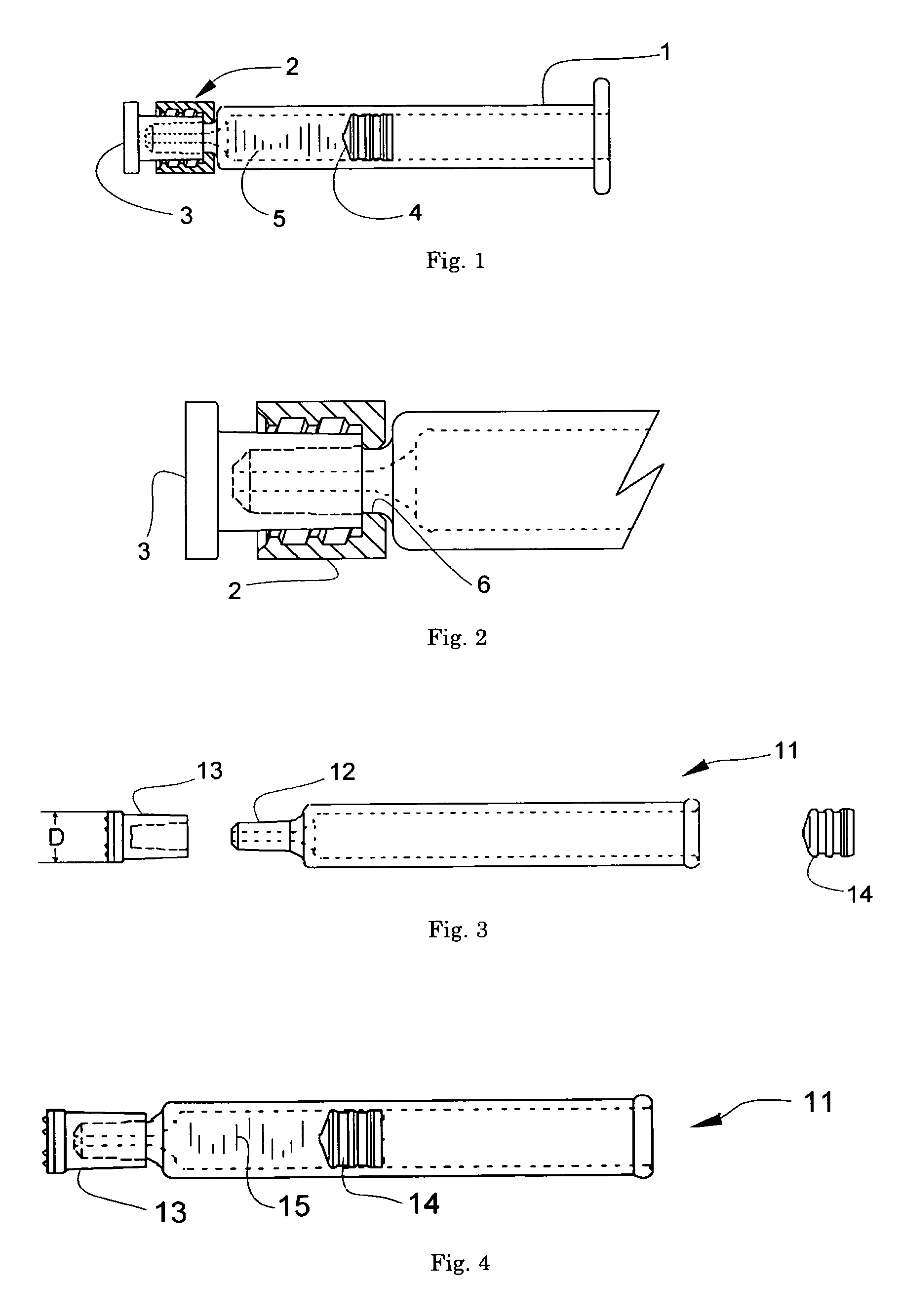
[0060]FIG. 3 illustrates a side view of a cylindrical glass syringe 11, a synthetic rubber cap 13 and a synthetic rubber gasket 14, which are used in the present invention. Numeral 12 indicates the male luer at the tip of the syringe. Regarding the cap 13, “D” indicates the maximum outer diameter, which is 7 mm in this example. FIG. 4 illustrates the parts shown in FIG. 3 which has been assembled. Numeral 15 indicates an injection liquid which has filled the syringe.

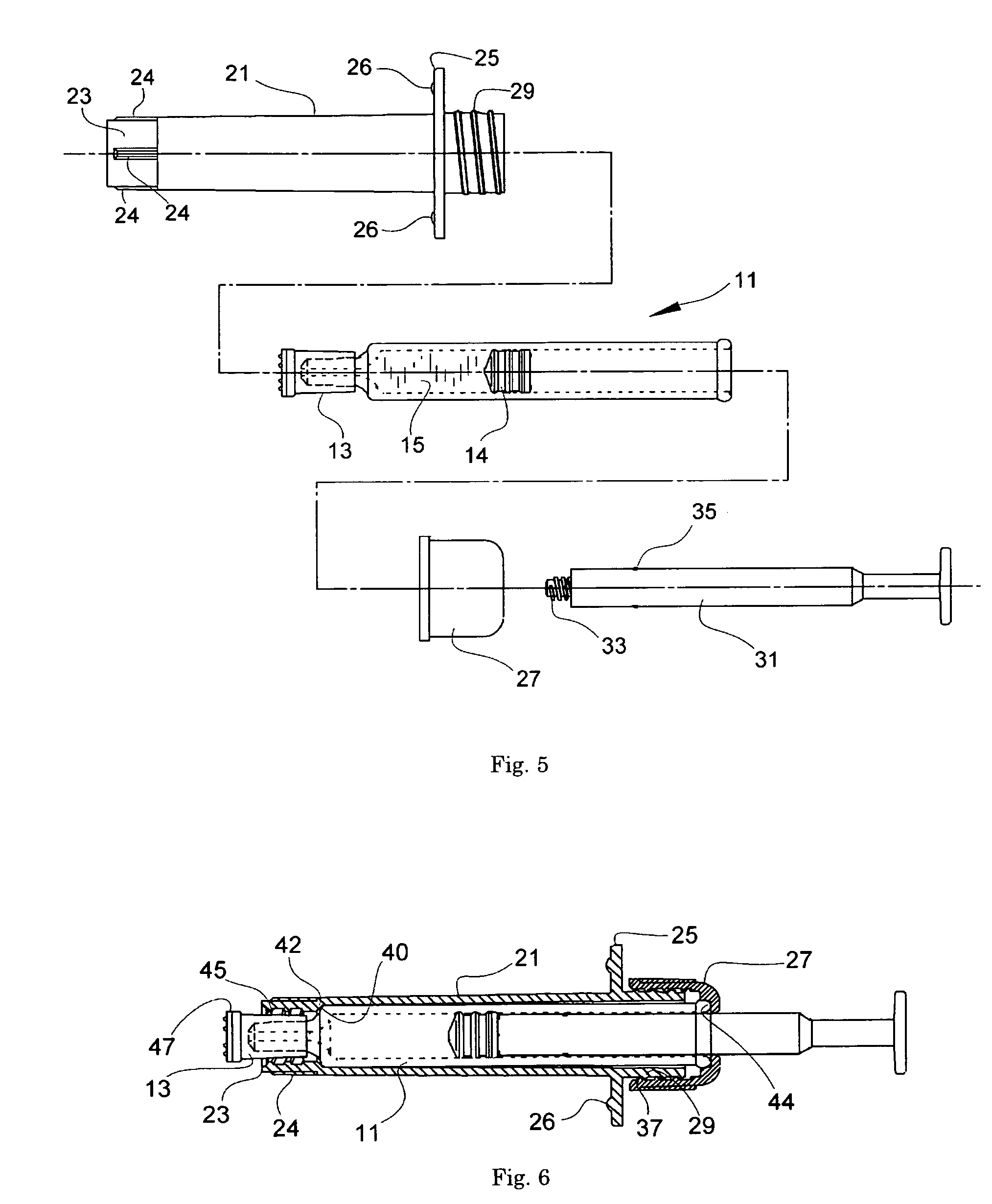
[0061]FIG. 5 is an assembly drawing illustrating a syringe holder before assembly and indicating the positional relationship of the parts when the syringe 11 filled with the injection liquid 15 is inserted into the syringe holder of the present invention and then a piston rod is attached to assemble the injection device. In the figure, numeral 21 indicates a barrel portion which constitutes a part of the syringe holder and is formed of polycarbonate. At the distal end of the barrel portion 21 extends a female-threaded sl...

example 2

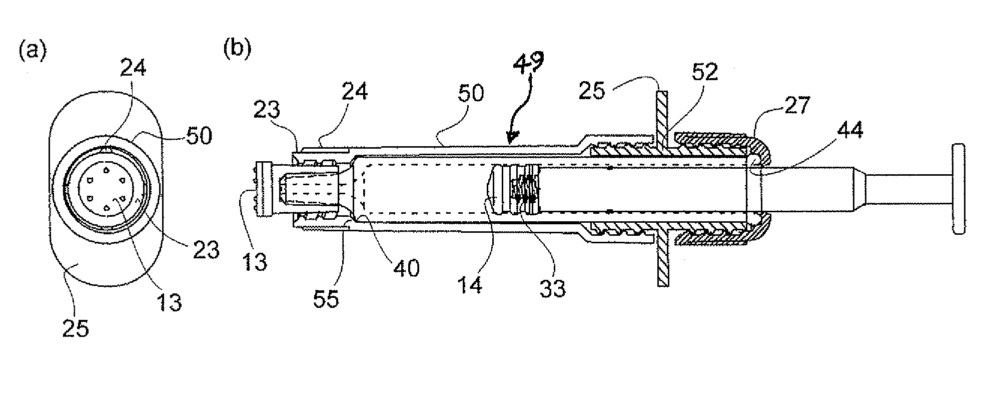
[0063]FIG. 7 illustrates an end view of the distal end (a) and a side view (b), of the assembled injection device of another example, with a portion shown in a cross section. In the figure, the syringe 11, cap 13, gasket 14 and piston rod 31 are identical to those in Example 1. This example differs from Example 1 in that the barrel portion 49 of the syringe holder here is composed of a distal portion 50 and a proximal portion 52. The finger rest 25 is integrally molded with the proximal portion 52 of the barrel portion, and the distal portion 50 of the barrel portion is screw-fixed, forward of the finger rest 25, on the proximal portion 52 of the barrel portion. While the wall of the syringe 11 has increased thickness at its proximal end 44 and, as a result, enlarged outer diameter there, the inner diameter of the proximal portion 52 of the barrel portion is smaller than the outer diameter of the distal end of the syringe. Therefore, the syringe 11 cannot forwardly advance from the ...


PUM


Abstract

An injection device adapted to the luer lock system and a syringe holder for making it is disclosed. The syringe holder for holding an inserted syringe, with a cap attached to the male luer at the tip, comprises a cylindrical barrel portion having an open distal end and an open proximal end, and a finger rest around the outer surface of the barrel portion at a position relatively closer to the proximal end, wherein a stopper means is provided at the inner surface of the barrel portion at the distal end thereof, the stopper means being designed to abut on the outer edge of the distal end of the syringe, and wherein a female-threaded sleeve extends forwardly from the distal end of the barrel portion, which is designed to surround the tip of the syringe and the cap, and wherein a proximal end cap is provided, at the proximal end of the barrel portion, which is designed to abut on the outer edge of the proximal end of the syringe, and has a bore to pass the piston rod through.

Description

FIELD OF THE INVENTION[0001]The present invention relates to a syringe holder designed to be used to build, with a syringe having a simple luer-type tip, an injection device which is adapted to the luer lock system, as well as an injection device comprising that holder and a syringe which is held by the holder.BACKGROUND OF THE INVENTION[0002]For connecting a syringe and a counterpart connection device such as a needle or a connection port of infusion tubing or an infusion pump, or the like, the simple luer fitting system is generally employed, which is achieved by fitting of a male luer provided at the tip of the former to a female luer provided in the latter. Further, in addition to the simple luer system, another type of system (luer lock system) has been employed for connection to, e.g., infusion tubing, where a female luer is screw-cramped around itself for the purpose of securely fix the fitting to prevent its easy displacement by external forces. As syringes that are also ada...

Claims


Application Information

Patent Timeline
Patent Type & Authority Patents(United States)
IPC IPC(8): A61M5/32
CPCA61M5/3129A61M5/344A61M5/347A61M2005/3104
Inventor SUGITA, KOUICHIMATSUMOTO, HIROSHI
Owner JCR PHARMA
Why Eureka
Try Eureka