Quick change chip removing drill bit

A drill bit and drill shank technology, applied in the field of quick-change chip evacuation drill bits, can solve problems such as affecting processing efficiency and processing quality, unsmooth chip removal, and increased wear, so as to ensure the quality of the machined surface, the service life of the tool, and the processing quality. and machining efficiency, the effect of improving tool durability

Pending Publication Date: 2019-08-09
JIANGSU TIANGONG PRECISION TOOLS CO LTD
View PDF0 Cites 0 Cited by
  • Summary
  • Abstract
  • Description
  • Claims
  • Application Information

AI Technical Summary

Problems solved by technology

Especially when drilling difficult-to-machine materials, because the main edge of the traditional twist drill is long and the cutting width is wide, the chips are curled into spiral coils, which occupies a large space, resulting in poor chip removal and difficult flow of cutting fluid. The cutting heat at the cutting edge of the twist drill tip rises sharply, and the cutting edge is in a semi-closed state during drilling. Due to the limitation of the drill groove space, the chips cannot be discharged smoothly in time, which is easy to cause chip blocking and entanglement, resulting in The hardness of the cutting edge decreases rapidly, the wear increases, and the cutting ability is lost. In severe cases, the drill bit can be twisted, and it is easy to pile up and jam in the drilling hole. The increase of drilling force will aggravate the wear of the drill bit, and even cause the bit to be broken or burned, reducing the service life of the drill bit. Affect processing efficiency and processing quality
[0003] During the processing of drilling tools, the type of the drill bit will be constantly replaced according to the needs. The current quick-change drill bit includes a drill shank, a drill rod, and a cutter head. The drill shank is provided with an annular groove. It also provides a certain axial limit and circumferential limit, but the axial limit and circumferential limit are still not very reliable, and the structure of the quick-change drill itself is relatively simple, and major changes cannot be made

Method used


Image

  • Quick change chip removing drill bit
  • Quick change chip removing drill bit
  • Quick change chip removing drill bit

Examples


Embodiment Construction

[0023] In order to deepen the understanding of the present invention, the present invention will be described in further detail below in conjunction with the accompanying drawings and embodiments, which are only used to explain the present invention and do not limit the protection scope of the present invention.

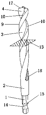
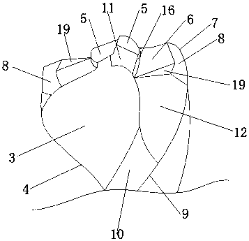
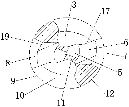
[0024] As shown in the figure: the technical solution of this embodiment is: a quick-change chip-cutting drill bit, including a coaxially arranged drill shank 1 and a cutter body 2, a spiral groove 3 is opened on the cutter body, and the cutter body The top end is a drill tip 4, and the drill tip 4 is provided with two centrally symmetrical flanks, and the flanks include a stepped first cutter face 5 and a second cutter face 6 and along the rear face of the drill bit. The back edge 7 is ground toward the second cutter face 6 to form a third cutter face 8, the inside of the spiral groove 3 is provided with a spiral chip guide arc surface 10 along the tail root edge 9 o...


PUM


Abstract

The invention provides a quick change chip removing drill bit. The quick change chip removing drill bit comprises a drill handle and a cutter body coaxial with the drill handle. A spiral groove is formed in the cutter body, a drill point is arranged at the top end of the cutter body, and two rear cutter faces in central symmetry are arranged on the drill point. Each rear cutter face comprises a stepped first cutter face, a stepped second cutter face, and a third cutter face formed by coping towards the second cutter face along a back ridge of a drill bit, a spiral chip guide cambered face is arranged in the spiral groove along a tail ridge of the drill bit, rear ditch ridges of the first cutter face, the second cutter face and the third cutter face and the tail ridge of the top of the cutter body are simultaneously coped in the chisel edge direction, a first coping face and a second coping face are formed on the front face of the cutter body, an annular groove is formed in the drill handle along the outer peripheral face, and multiple hemispherical blind holes are formed in the drill handle.

Description

technical field [0001] The invention belongs to the technical field of tools, and in particular relates to a twist drill, especially a quick-change chip-cutting drill. Background technique [0002] With the continuous development of science and technology, new materials are constantly emerging, and new requirements are constantly put forward for drill bits. Especially when drilling difficult-to-machine materials, because the main edge of the traditional twist drill is long and the cutting width is wide, the chips are curled into spiral coils, which occupies a large space, resulting in poor chip removal and difficult flow of cutting fluid. The cutting heat at the cutting edge of the twist drill tip rises sharply, and the cutting edge is in a semi-closed state during drilling. Due to the limitation of the drill groove space, the chips cannot be discharged smoothly in time, which is easy to cause chip blocking and entanglement, resulting in The hardness of the cutting edge dec...

Claims


Application Information

Patent Timeline
Patent Type & Authority Applications(China)
IPC IPC(8): B23B51/02
CPCB23B51/02
Inventor 朱小坤何建国
Owner JIANGSU TIANGONG PRECISION TOOLS CO LTD
Why Eureka
Try Eureka