Thermally actuated hot and cold water mixing valve configured to minimize valve hunting

a technology of hot and cold water mixing valve and valve hunting, which is applied in the direction of valve operating means/release devices, process and machine control, instruments, etc., can solve the problems of reducing unable to achieve stable temperature control, and the size of equipment itself is limited in view of the installation environment, so as to prevent hunting and improve the accuracy of temperature control

Active Publication Date: 2013-01-15
TOTO LTD +1
View PDF12 Cites 11 Cited by
  • Summary
  • Abstract
  • Description
  • Claims
  • Application Information

AI Technical Summary

Benefits of technology

[0038]Thus, according to the hot and cold water mixing valve of the present invention, it is possible to prevent hunting and improve the accuracy of temperature control.

Problems solved by technology

Incidentally, in the conventional hot and cold water mixing valve as described above, the mixture of the hot water and water having been insufficiently mixed may reach around the temperature sensitive spring depending on pressure magnitudes of the hot water and cold water flowing into the hot and cold water mixing valve.
Further, since the temperature sensitive spring used for the conventional hot and cold water mixing valve has a good response to temperature changes, if the insufficiently mixed water passes by the temperature sensitive spring, expansion / shrink operation takes place frequently according to the temperature changes of the temperature sensitive spring.
As a result, a hunting phenomenon occurs and the stable temperature control may not be carried out.
However, as for the hot and cold water mixing valve, the size of the equipment itself is limited in view of installation environment etc.
Therefore, it is difficult to sufficiently reserve the space for mixing the hot water and cold water inside the hot and cold water mixing valve.

Method used


Image

  • Thermally actuated hot and cold water mixing valve configured to minimize valve hunting
  • Thermally actuated hot and cold water mixing valve configured to minimize valve hunting
  • Thermally actuated hot and cold water mixing valve configured to minimize valve hunting

Examples


Embodiment Construction

[0093]Hereafter, the preferred embodiments of the present invention will be described with reference to the drawings.

[0094]Firstly, a first preferred embodiment of the present invention will be described with reference to FIG. 2.

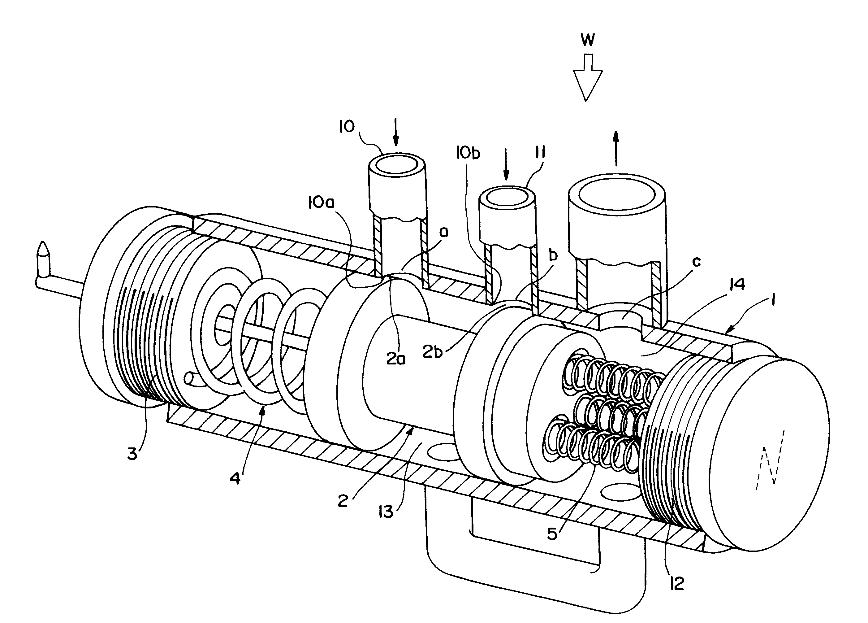
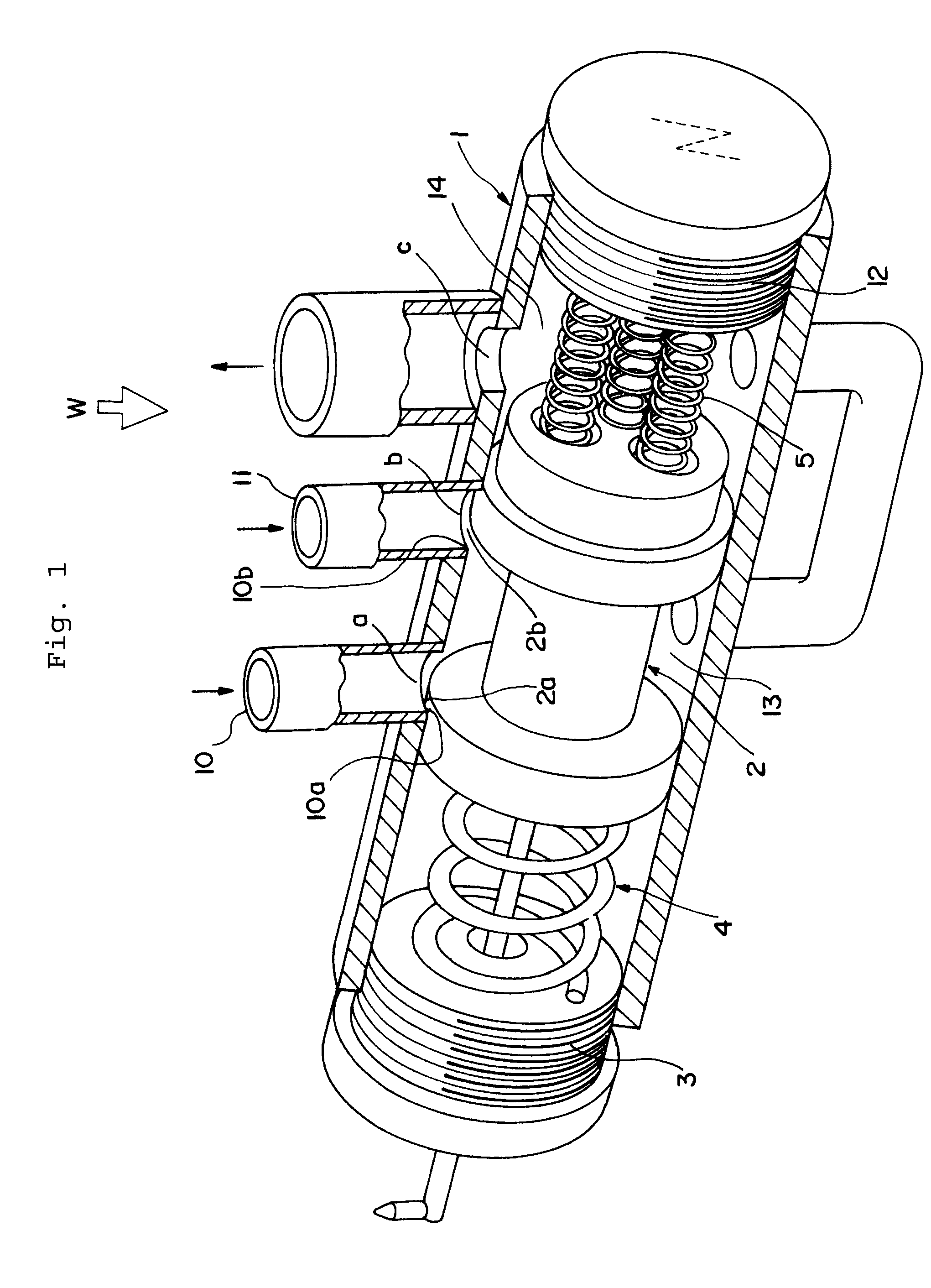
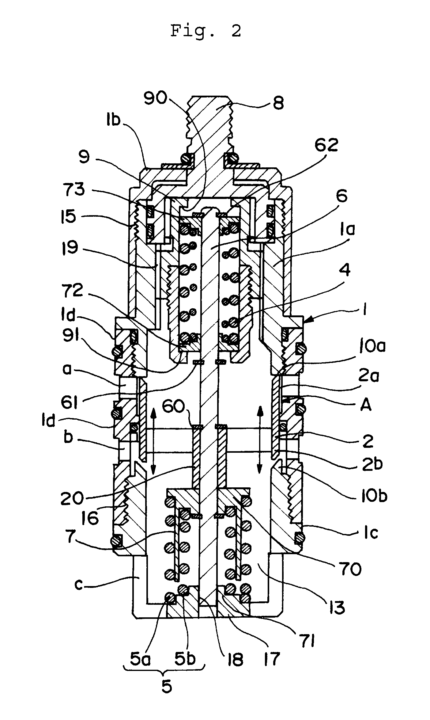
[0095]FIG. 2 shows a hot and cold water mixing valve of the first preferred embodiment of the present invention. Although not shown, the hot and cold water mixing valve of the first preferred embodiment is provided with an outer casing used as an outer box, and a main body member in the shape of a cartridge which is removably engaged with and inserted into the outer casing. The main body member is assembled so that a control valve mechanism A may be accommodated in a cylindrical casing 1.

[0096]The casing 1 is provided with a cylindrical main body 1a, a cover member 1b which is in the shape of a cap, has a bottom, and is threadedly connected to one end side of the cylindrical main body 1a, and a cylindrical valve seat member 1c. A cylindrical middle case comp...


PUM


Abstract

A hot and cold water mixing valve including a temperature adjusting dial, and a cylindrical casing having formed therein a hot water inlet and a cold water inlet is provided with a control valve member in which one end thereof is subjected to a load from a biasing member and the other end is subjected to a load from an actuator. By balancing between the loads applied by the biasing member and the actuator, a mixture ratio between the hot water which flows in through the hot water inlet and the cold water which flows in through the cold water inlet is adjusted. A temperature adjuster adjusts a position of the control valve member through the biasing member and includes a tapered skirt portion, which spreads in a radial direction, at an end on the control valve member side thereof.

Description

TECHNICAL FIELD[0001]The present invention relates to a technology of a hot and cold water mixing valve.BACKGROUND ART[0002]Conventionally, a hot and cold water mixing valve has been used for controlling a temperature of a mixture of hot and cold water by biasing a movable valve member for changing a mixture ratio of hot water to cold water by means of a spring made of a shape memory alloy whose spring constant changes with temperature. Such a hot and cold water mixing valve is disclosed in Patent Document 1, for example.[0003]Patent Document 1 discloses a hot and cold water mixing valve which uses a spring made of a shape memory alloy as a temperature sensitive actuator, and is arranged such that mixed water passes outside the spring made of the shape memory alloy. Further, Patent Document 1 discloses a structure where a seat surface part to which a generation load is applied is formed at one end of the spring made of the shape memory alloy and a movable valve member is moved accor...

Claims


Application Information

Patent Timeline
Patent Type & Authority Patents(United States)
IPC IPC(8): G05D23/02
CPCF16K11/07G05D23/1353F16K31/003F16K19/006Y10T137/7737Y10T137/87652
Inventor TODAKA, KENSAKUMATSUI, HIDEYUKISEKI, EIJINEGISHI, ISAO
Owner TOTO LTD
Why Eureka
Try Eureka