Mounting appratus for slide rail

a technology for mounting apparatuses and slide rails, which is applied in the direction of dismountable cabinets, curtain suspension devices, lighting support devices, etc., can solve the problems of time-consuming and inconvenient installation or uninstallation of the outer slide rail to or from the brackets

Active Publication Date: 2013-01-15
FULIAN PRECISION ELECTRONICS (TIANJIN) CO LTD
View PDF10 Cites 99 Cited by
  • Summary
  • Abstract
  • Description
  • Claims
  • Application Information

AI Technical Summary

Benefits of technology

[0005]A conventional slide rail assembly for a drawer and a desk includes an outer slide rail mounted to the desk, an inner slide rail mounted to the drawer, and an intermediate slide rail mounted between the outer and inner slide rails. The intermediate slide rail is extendable relative to the outer slide rail, and the inner slide rail is extendable relative to the intermediate slide rail, thus the drawer can be extended a distance out from the desk. A plurality of screws is used for mounting the outer slide rail to a bracket of the desk. Therefore, installing or uninstalling the outer slide rail to or from the bracket can be inconvenient and time-consuming.

Problems solved by technology

Therefore, installing or uninstalling the outer slide rail to or from the bracket can be inconvenient and time-consuming.

Method used


Image

  • Mounting appratus for slide rail
  • Mounting appratus for slide rail
  • Mounting appratus for slide rail

Examples


Embodiment Construction

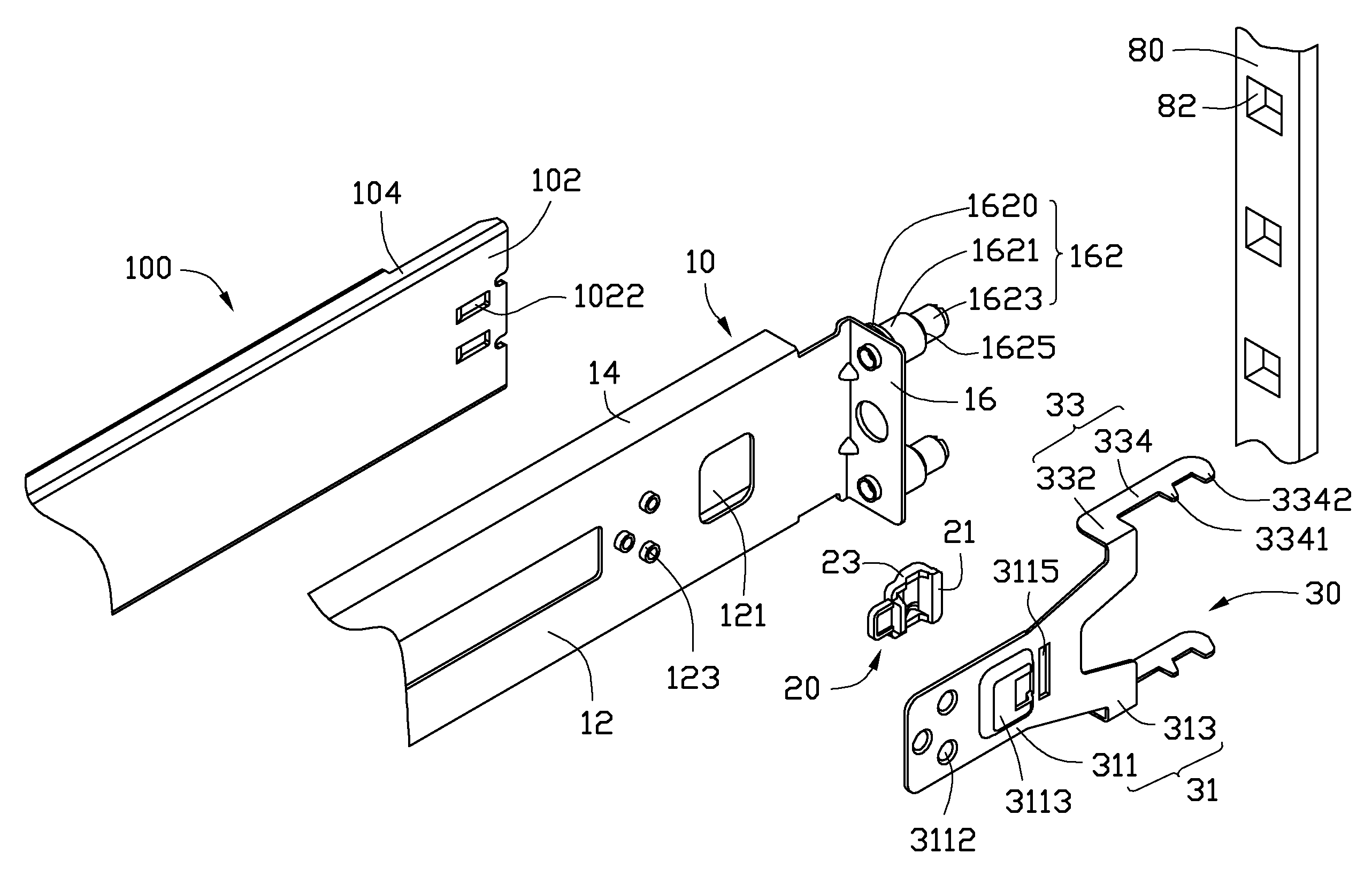
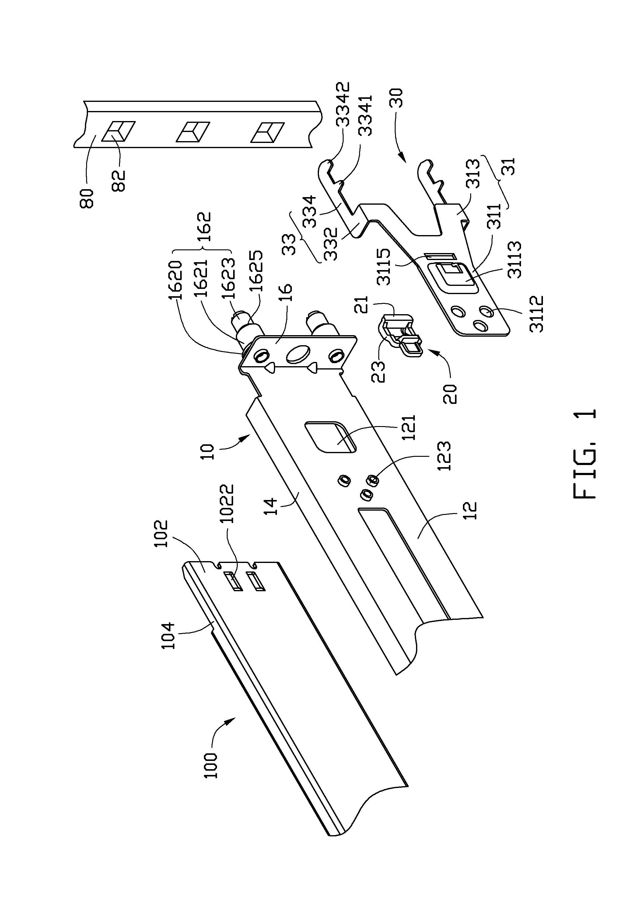
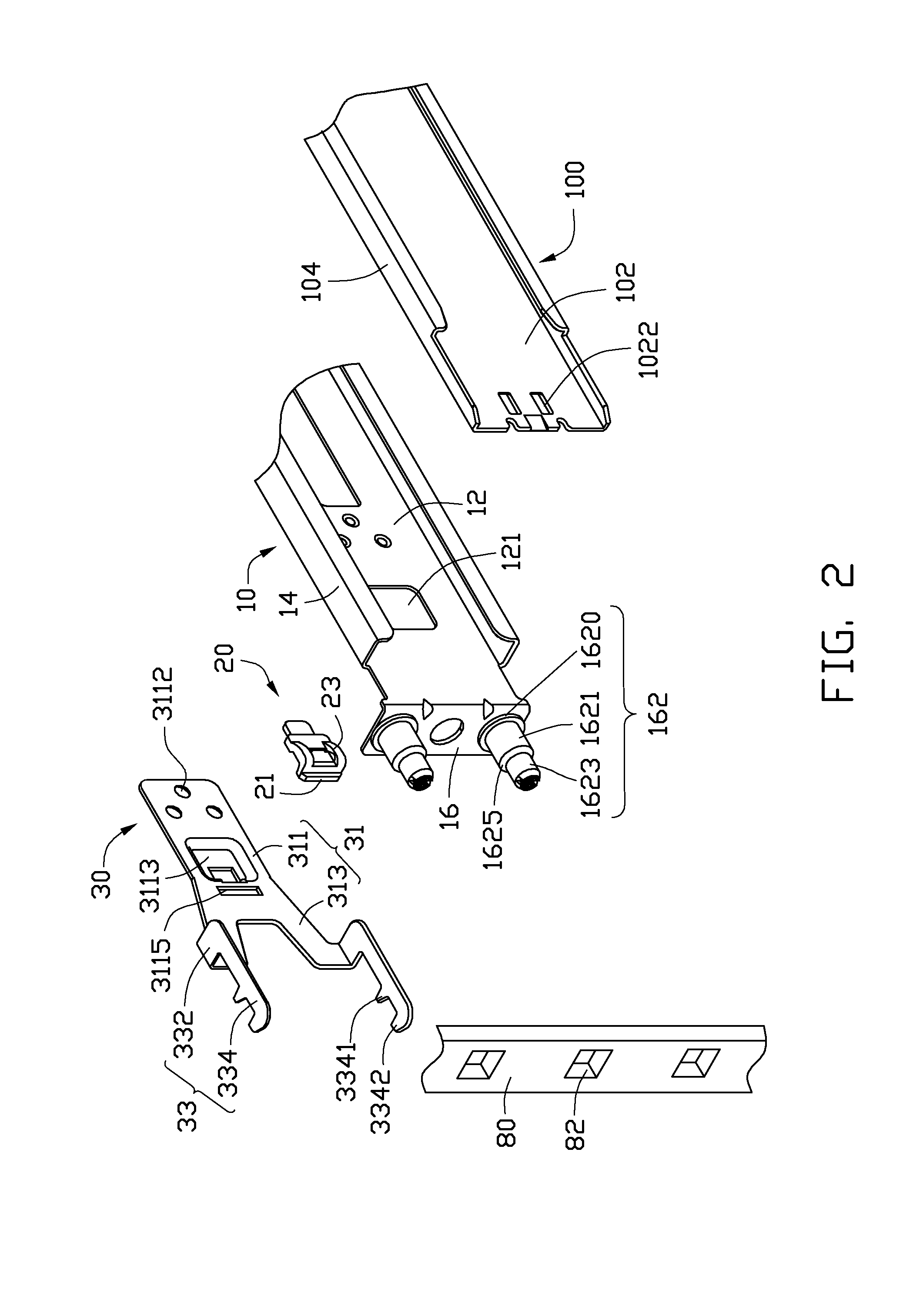
[0011]Referring to FIGS. 1, 2, and 6, an embodiment of a mounting apparatus is provided for mounting a slide rail 100 to a component rack. The component rack may include a plurality of first rack posts 80 defining a plurality of rectangular through holes 82 (shown in FIGS. 1 and 2), or include a plurality of second rack posts 90 defining a plurality of round through holes 62 (shown in FIG. 6). The mounting apparatus includes a supporting bracket 10, an actuating member 20, and a latch member 30.

[0012]The slide rail 100 has a substantially C-shaped cross section, and includes a web 102 and two flanges 104 extending from opposite sides of the web 102, respectively. The web 102 defines two slots 1022 substantially adjacent to a front end of the slide rail 100.

[0013]The supporting bracket 10 includes a side plate 12, two flanges 14 substantially perpendicularly extending inwards from opposite sides of the side plate 12, and an end plate 16 extending outwards from a front end of the slid...


PUM


Abstract

A mounting apparatus is provided for mounting a slide rail to a rack post defining a plurality of through holes. The mounting apparatus includes a supporting bracket slidably mounted to the slide rail, and a resilient latch member. The supporting bracket includes an end plate at the front end with two inserting pins extending from a front surface of the end plate and engaged in corresponding through holes of the rack post. The latch member includes a middle plate retained to the supporting bracket, and a latch arm extending forwards. The latch member is operable to be deformed to make the latch arm abut a front surface of the rack post, to prevent the inserting pin from retracting from corresponding through holes.

Description

BACKGROUND[0001]1. Technical Field[0002]The present invention relates to mounting apparatuses and, more particularly, to a mounting apparatus for a slide rail.[0003]2. Description of the Related Art[0004]Traditionally, a slide rail is used between two objects that can move relative to each other, such as between a desk and a drawer, or a server and a rack.[0005]A conventional slide rail assembly for a drawer and a desk includes an outer slide rail mounted to the desk, an inner slide rail mounted to the drawer, and an intermediate slide rail mounted between the outer and inner slide rails. The intermediate slide rail is extendable relative to the outer slide rail, and the inner slide rail is extendable relative to the intermediate slide rail, thus the drawer can be extended a distance out from the desk. A plurality of screws is used for mounting the outer slide rail to a bracket of the desk. Therefore, installing or uninstalling the outer slide rail to or from the bracket can be inco...

Claims


Application Information

Patent Timeline
Patent Type & Authority Patents(United States)
IPC IPC(8): A47B96/00
CPCA47B88/044H05K7/1489A47B88/43
Inventor PENG, WEN-TANGYU, MO-MINGGU, GUANG-HUACHEN, ZE-HONG
Owner FULIAN PRECISION ELECTRONICS (TIANJIN) CO LTD
Why Eureka
Try Eureka