Gas turbine engine with dual compression rotor

a gas turbine engine and compression rotor technology, applied in the direction of machines/engines, mechanical equipment, radial flow pumps, etc., can solve the problems of engine operation efficiency only within a relatively narrow band, engine operation efficiency is not easy to achieve during off-design conditions, and the design complexity and life cycle cost increas

Inactive Publication Date: 2013-01-22
US SEC THE AIR FORCE THE
View PDF28 Cites 15 Cited by
  • Summary
  • Abstract
  • Description
  • Claims
  • Application Information

AI Technical Summary

Benefits of technology

[0013]The gas turbine engine of the present invention (also referred to as the Revolutionary Innovative Turbine Engine (RITE)) incorporates technology that provides versatile mission capabilities in one configuration, including: maximum engine thrust for minimum takeoff and climb; minimum engine fuel consumption and vehicle drag for maximum range; and maximum power generation to meet increasing vehicle and weapon requirements.
[0014]The RITE cycle has infinite variability and applicability because each rotating stage can be controlled independently. The technology features that make up the RITE cycle include, but are not limited to: a dual compression rotor (DCR) for higher overall pressure ratios with minimum number of rotor stages; independently supported rotors (ISR) using hybrid and / or magnetic bearings for support in lieu of shafts; axial and centrifugal compressors controlled independently for optimum performance match; substantial reduction in overall engine length and weight; a dedicated turbine attached to each fan / compressor rotor (cooling air on-board if needed to control turbine metal temperatures (cooling air provided directly to turbine through radial passages in DCR); low turbine bore temperatures due to cool compressor inlet airflow bathing; hot sections located outboard for overall reduction of internal temperatures for bearings and mechanical systems; reduced thermal and centripetal bore growth for tighter turbine tip clearance; use of nickel material at high compressor exit temperature region; and inter turbine burners (ITB) to boost temperature and work capability after each turbine to lower maximum turbine temperature and net energy loss throughout the engine.
[0015]Other features include: fan-on-turbine which eliminates the need for a low pressure shaft; an internal starter for engine starting; generators that can be controlled by controlling the speed of each rotor separately for optimized operability (stage matching, power extraction and management (all electric, no gearbox required)); engine core can run at design point throughout mission profile because thrust requirements for flight can be independently controlled by the ITBs, greatly reducing engine thermal cycles and maintenance costs and increasing engine life; and a free / power turbine that matches inlet airflow to reduce vehicle drag (at lower power settings during vehicle cruise or loiter (the power turbine temperature can be independently increased to match inlet design flow by compensating for decreased fan flow). The power turbine drives a power generator which maximizes the use of gas path energy / efficiency, extracts energy to reduce engine gas temperature, and reduces power generation impact on the engine cycle. At lower power settings during vehicle cruise or loiter the power turbine temperature can be independently increased to maximize power extraction for avionics or directed energy weapons.

Problems solved by technology

Such engines, however, typically operate efficiently only within a relatively narrow band of engine speeds.
The high temperatures and pressures drive up design complexity and life cycle costs (development, production, maintenance).
Also, these turbine engines are designed for optimum performance at one design point which causes the engines to operate less efficiently during off design conditions.
That is, conventional turbine engines cannot produce the optimum higher pressure ratios at lower cruise power settings.
Another limitation of conventional turbine engines is the use of a rotor for each compressor and turbine stage, as well as a connecting shaft linking the compressor and turbine, which significantly increases the engine length, weight, and cost.
Also, a limiting factor is the ability of steel, nickel, ceramic, or other engine materials to withstand extreme heat and pressure.
These extreme temperatures require elaborate / complex secondary flow cooling circuits to maintain acceptable material properties, especially at the high pressure turbine bores.
Unfortunately, these cooling systems reduce engine performance and add undesirable weight.
Maintaining a gap between the rotor tips and the engine shroud to account for thermal growth causes large tip leakage losses and lower component performance and efficiency.
Conventional turbine engines also have complex bearing systems that operate near maximum temperature limits and endure extreme shaft dynamics.

Method used


Image

  • Gas turbine engine with dual compression rotor
  • Gas turbine engine with dual compression rotor
  • Gas turbine engine with dual compression rotor

Examples


Embodiment Construction

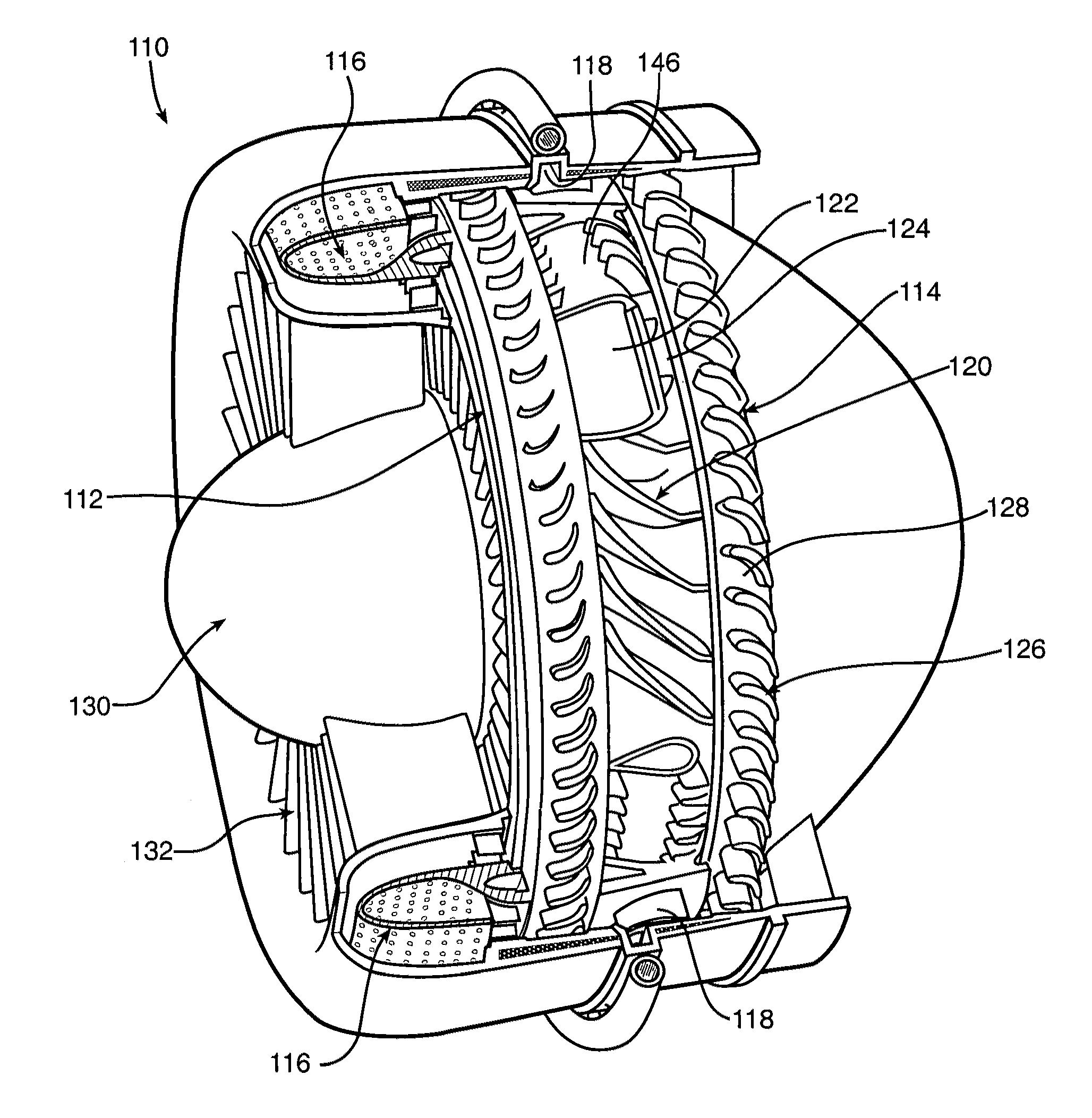
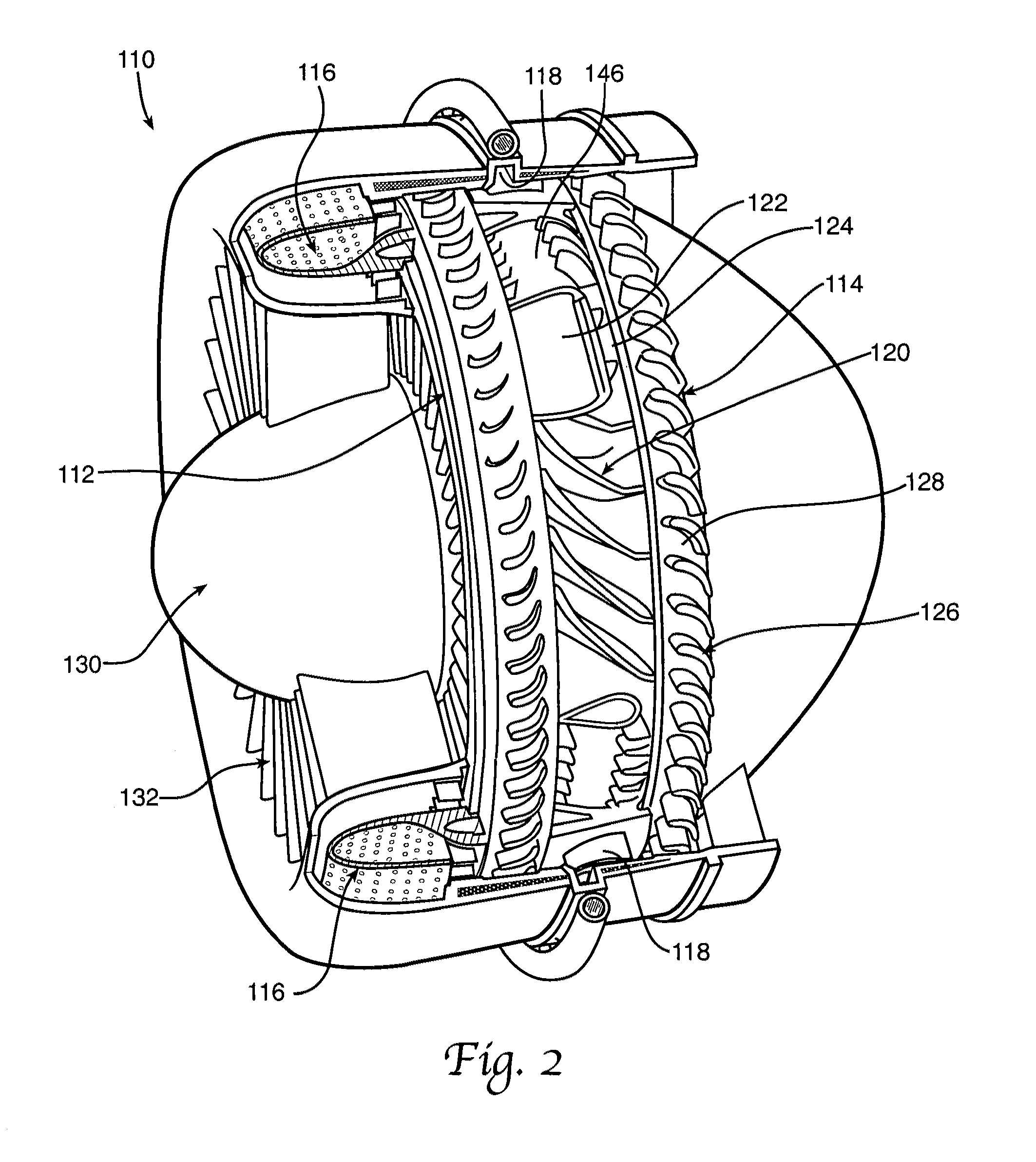
[0037]Referring to the drawings, FIG. 2 shows a cut-away view of the engine of the present invention, also called the revolutionary innovative turbine engine (RHE) 110. The engine 110 generally includes a dual compression rotor 112, a centrifugal compression rotor 114, a combustion chamber 116, and an inter-turbine burner 118. The rotors 112 and 114 are independently supported about a common axis of rotation. Independent support allows the rotors 112 and 114 to rotate independently of each other as well as rotate in the opposite or same direction. For example, the dual compression rotor may rotate clockwise or counterclockwise, and the centrifugal compression rotor may rotate in the opposite direction. Alternatively, the rotors 112 and 114 may both rotate clockwise or counterclockwise. The dual compression rotor 112 is described in more detail with reference to FIG. 6.

[0038]The centrifugal compression rotor 114 includes a plurality of blades 120 designed for radial compression of ai...


PUM


Abstract

The present invention provides a gas turbine engine including a first combustion chamber, a dual compression rotor positioned behind the combustion chamber, and a centrifugal compression rotor positioned behind the dual compression rotor.

Description

CROSS REFERENCE TO RELATED APPLICATIONS[0001]The present application relates to and claims priority to U.S. Provisional Patent Application No. 60 / 910,266 filed Apr. 5, 2007, entitled “Revolutionary Innovative Turbine Engine” and U.S. Provisional Patent Application No. 60 / 910,273 filed Apr. 5, 2007, entitled “Dual Compression Rotor”. Patent Application Nos. 60 / 910,266 and 60 / 910,273 are hereby incorporated by reference.RIGHTS OF THE GOVERNMENT[0002]The invention described herein may be manufactured and used by or for the Government of the United States for all governmental purposes without the payment of any royalty.FIELD OF THE INVENTION[0003]The present invention relates generally to gas turbine engines, and in particular, relates to a gas turbine engine having a dual compression rotor.BACKGROUND OF THE INVENTION[0004]Gas turbine engines are well-known for providing propulsion and power production. Compared to other engine types, a gas turbine engine has the advantage that its roto...

Claims


Application Information

Patent Timeline
Patent Type & Authority Patents(United States)
IPC IPC(8): F02K3/00F02C5/00F02C3/00F02C3/04
CPCF02C3/073F02C3/145F02K3/068F04D25/045F04D1/08F04D19/022Y02T50/672Y02T50/60
Inventor DALE, MARK R.
Owner US SEC THE AIR FORCE THE
Why Eureka
Try Eureka