
Bowden cable adjusting device and mounting process

a technology of adjusting device and bowden cable, which is applied in the direction of braking system, shaft, railway braking system, etc., can solve the problems of bowden cable adjusting device from being adjusted, and achieve the effect of facilitating the mounting and handling of the bowden cable adjusting device, low design effort, and simple and convenient operation

Active Publication Date: 2013-01-29
AL KO ACTUATION SYST
View PDF18 Cites 1 Cited by
  • Summary
  • Abstract
  • Description
  • Claims
  • Application Information

AI Technical Summary

Benefits of technology

[0006]The mounting process and the Bowden cable adjusting device with the mounting securing means have the advantage that the Bowden cable adjusting device and the Bowden cable arrangement always have the same, defined configuration for mounting the Bowden cable and for putting into operation. This simplifies and facilitates the mounting and handling of the Bowden cable adjusting device. In addition, the mounting securing means prevents the Bowden cable adjusting device from being adjusted in an undesired manner during transportation or on other occasions. The design of the transmission element with means securing against rotation also counteract such an adjustment.
[0007]The mounting process makes it possible to connect an actuating member and one or more Bowden cables in a rapid and simple operation and to set the Bowden cable arrangement, which is closed hereby. The correct distance between the actuating member and the Bowden cables is set now. The use of a mounting tool makes it possible to hold the Bowden cable or the Bowden cables in the correct stretched position. Adjustment of the Bowden cable arrangement is possible by simply using the actuating member.
[0008]The mounting securing means can be overcome and deactivated in a simple manner for mounting and putting into operation. Removal of securing parts is not necessary now. It is sufficient to stationarily support the transmission element with the mounting tool and to deactivate the mounting securing means by actuating an adjusting member, e.g., a hand brake lever, by removing, e.g., breaking off or breaking into pieces the support element. The support element can be discarded and disposed of in a simple manner. As an alternative, it may remain at the transmission element. The circumstance that functional parts of the Bowden cable according to the present invention, which are needed anyway, can be used for the mounting securing means and maintain their function after removal of the support element is advantageous here as well.
[0009]The support element with its predetermined breaking elements, e.g., one or more weakened areas of the wall, can be broken off by the force of the hand and by the adjusting force during the actuation of the hand brake lever. The force needed to break off the mounting securing means is weaker due to the predetermined breaking elements than the force needed for adjusting or the force of the hand. No other tools are necessary for mounting and putting into operation the Bowden cable adjusting device and the Bowden cable arrangement aside from the mounting tool, which can have only a supporting function for the transmission element during the engagement of the hand brake lever. The preferred design embodiment of the Bowden cable adjusting device with the housing, locking means and transmission element is also advantageous. The embodiment being claimed requires only a low design effort and is especially cost-effective and reliable in operation. In addition, there is a high level of trouble-free operation.

Problems solved by technology

In addition, the mounting securing means prevents the Bowden cable adjusting device from being adjusted in an undesired manner during transportation or on other occasions.

Method used


Image

  • Bowden cable adjusting device and mounting process
  • Bowden cable adjusting device and mounting process
  • Bowden cable adjusting device and mounting process

Examples


Embodiment Construction

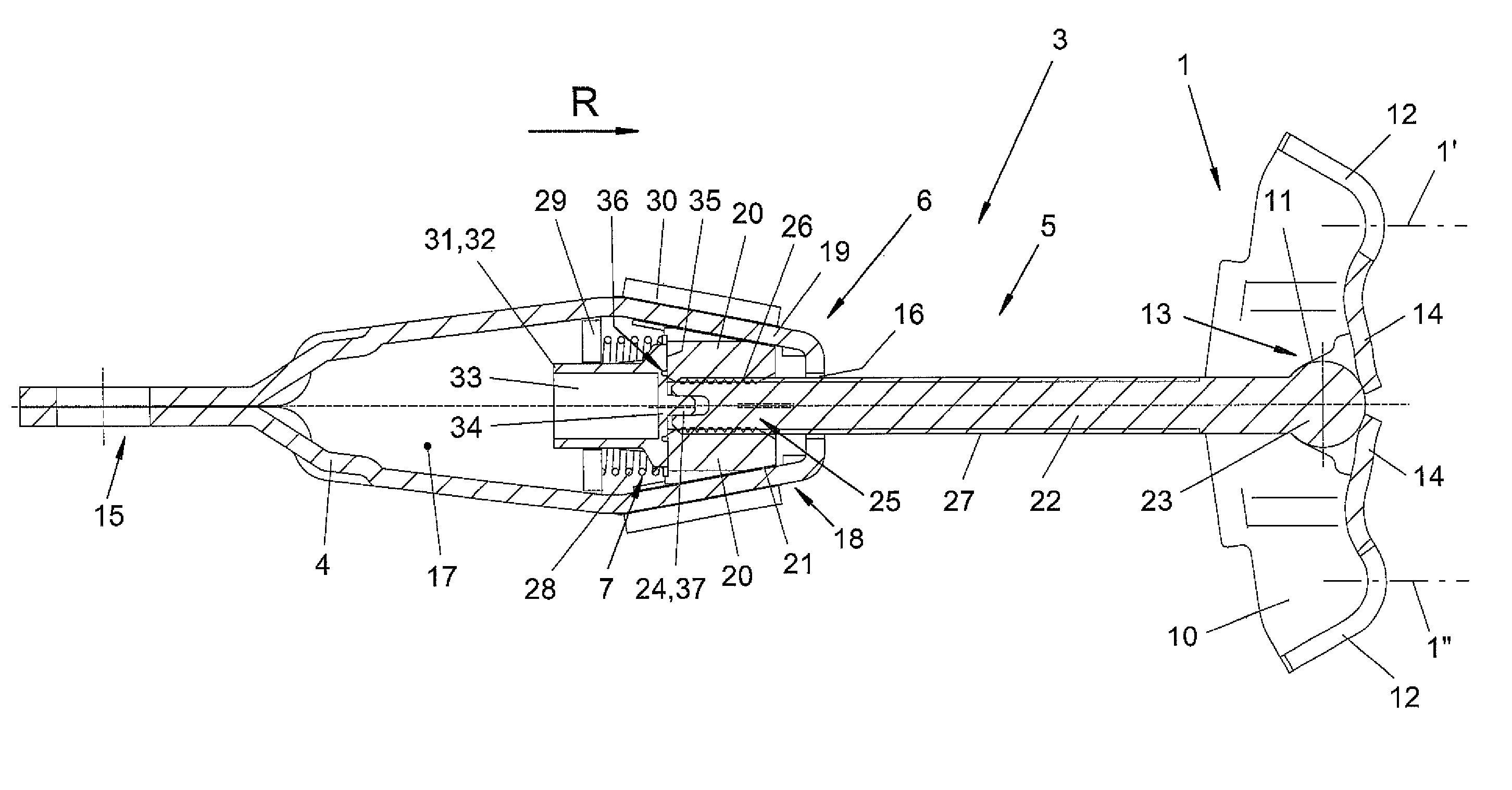
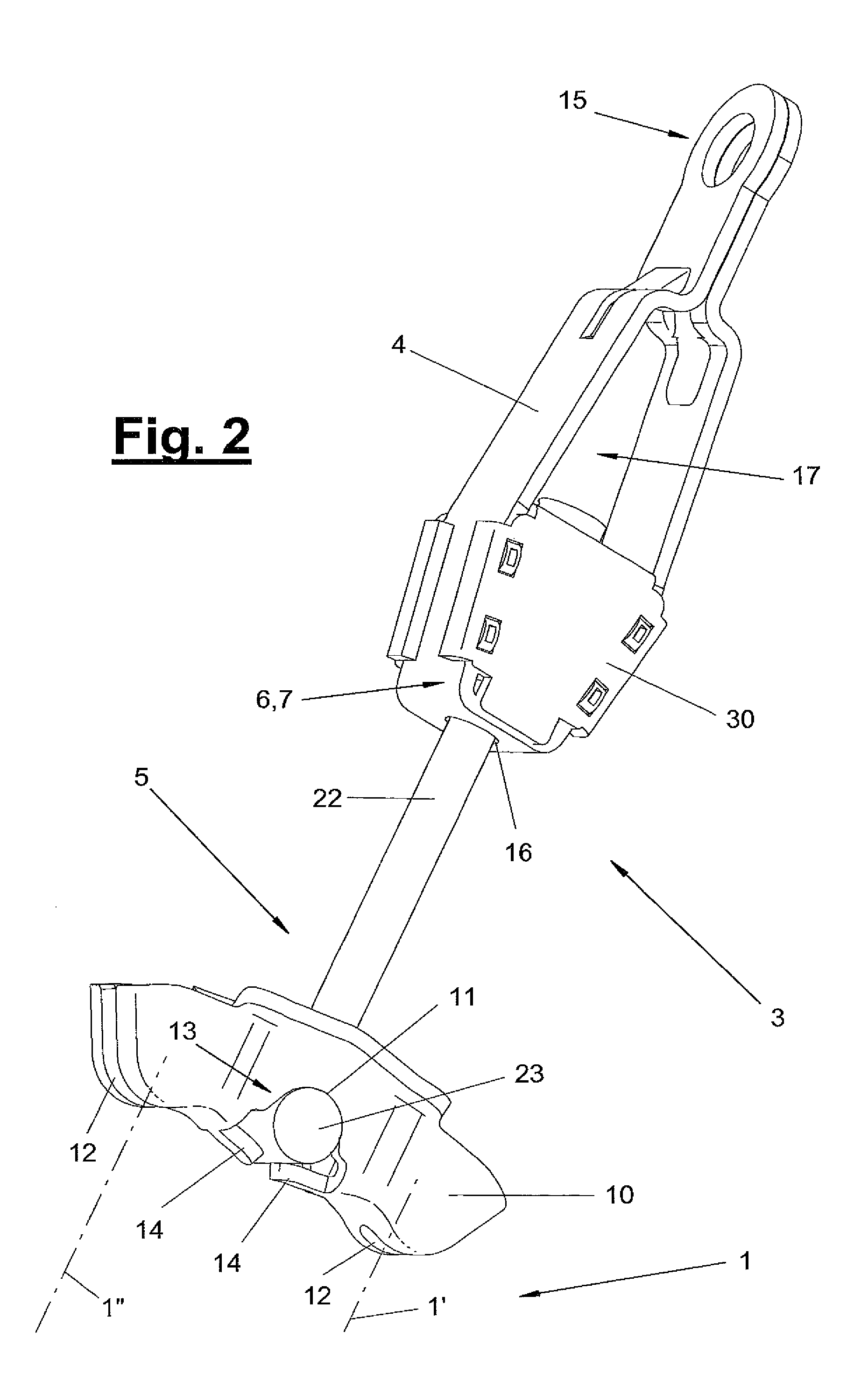
[0030]Referring to the drawings in particular, the present invention pertains to a Bowden cable adjusting device (3) for a Bowden cable arrangement (1) with one or more Bowden cables (1′, 1″). The present invention pertains, furthermore, to an adjusting or mounting process, to the Bowden cable arrangement (1) and to a vehicle equipped therewith.

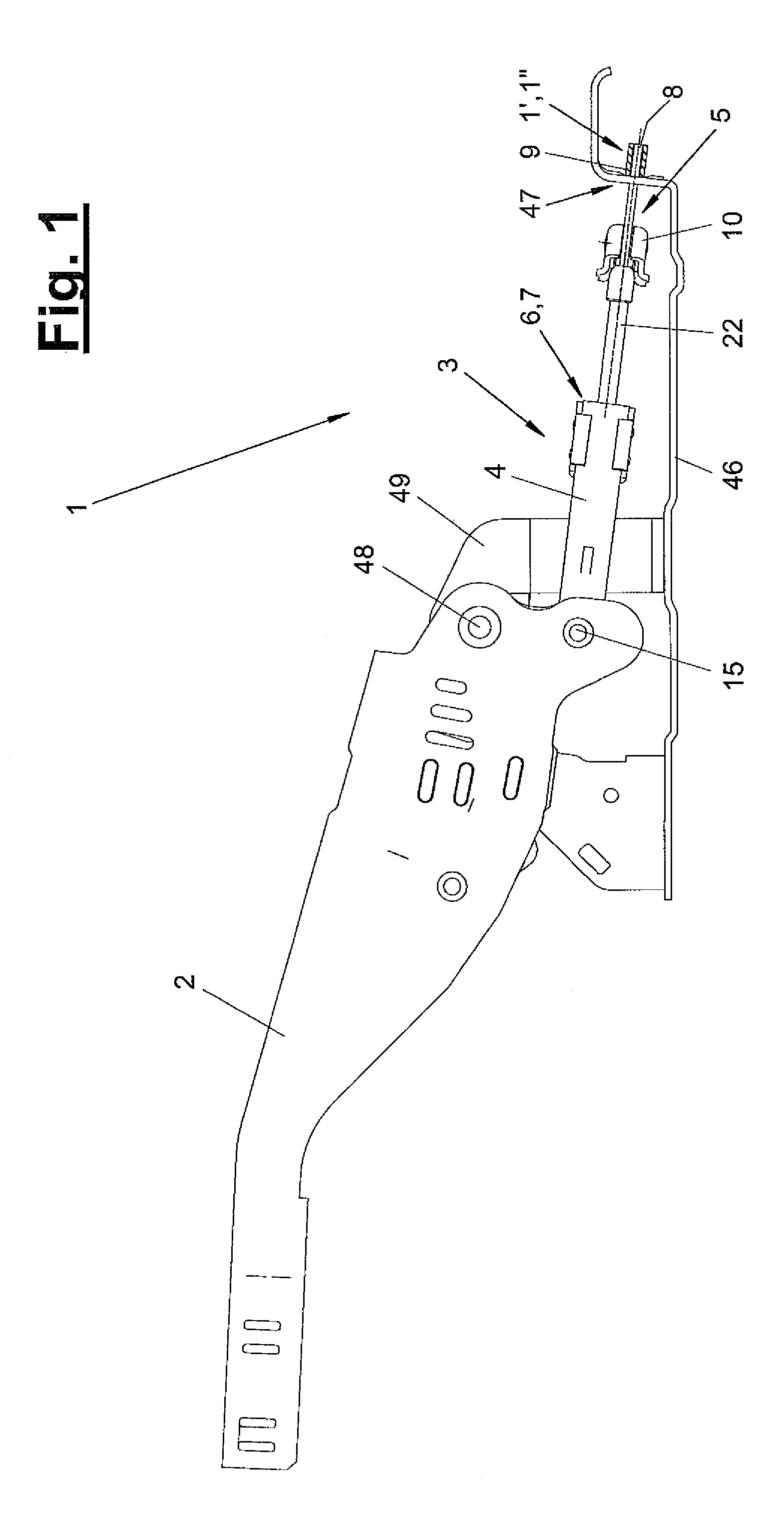
[0031]FIG. 1 shows a side view of a Bowden cable arrangement (1) before putting into operation. In the embodiment being shown, the Bowden cable arrangement (1) has two parallel Bowden cables (1′, 1″), which have an inner tensile cable (8) and a surrounding sheath (9) each. The number of Bowden cables (1′, 1″) may vary and be fewer or more than two. The Bowden cables (1′, 1″) are connected to an actuating member (2) by means of a Bowden cable adjusting device (3).

[0032]At the beginning, the actuating member (2) and the Bowden cables (1′, 1″) are arranged separated and at spaced locations from one another. During mounting, they are connected to...


PUM


Abstract

A Bowden cable adjusting device is provided for one or more Bowden cables (1′, 1″). The Bowden cable adjusting device (3) has a housing (4) with a detachable locking device (6) for adjustably connecting the housing (4) to a transmission element (5), which can be connected to one or more Bowden cables (1′, 1″). The Bowden cable adjusting device (3) has a mounting securing device (7) for the transmission element (5). The mounting securing device (7) can be deactivated. A process for mounting and adjusting a Bowden cable arrangement is also provided, wherein the mounting securing device (7) may be deactivated and the Bowden cable adjusting device (3) is shortened while adjusting the distance between the actuating member (2) and the Bowden cable (1′, 1″).

Description

CROSS REFERENCE TO RELATED APPLICATIONS[0001]This application claims the benefit of priority under 35 U.S.C. §119 of German Utility Model 20 2007 010 787.0 filed Aug. 1, 2007, the entire contents of which are incorporated herein by reference.FIELD OF THE INVENTION[0002]The present invention pertains to a Bowden cable adjusting device for one or more Bowden cables and a mounting process for mounting and adjusting a Bowden cable arrangement.BACKGROUND OF THE INVENTION[0003]Bowden cables are adjusted in practice by adjusting the Bowden cable sheath at the point of attachment. This is a manual adjustment.[0004]Furthermore, it is known that to compensate wear, Bowden cables can be provided with an automatic Bowden cable adjusting device, in which the cable is restretched by means of a spring with the Bowden cable released.SUMMARY OF THE INVENTION[0005]The object of the present invention is to show an improved Bowden cable adjusting device.[0006]The mounting process and the Bowden cable a...

Claims


Application Information

Patent Timeline
Patent Type & Authority Patents(United States)
IPC IPC(8): F16C1/22
CPCB60T7/102B60T7/108B60T11/046F16C1/14F16C1/223Y10T74/20462F16C2361/45Y10T74/20402Y10T74/2042
Inventor KAINZNER, CHRISTOPH
Owner AL KO ACTUATION SYST
Learn More