
Headrest for a patient-bearing surface

a technology for patient-bearing surfaces and headrests, which is applied in the field of headrests for patient-bearing surfaces, can solve the problems of unsuitable support and not well-adapted to human shap

Active Publication Date: 2013-01-29
MAQUET GMBH
View PDF8 Cites 5 Cited by
  • Summary
  • Abstract
  • Description
  • Claims
  • Application Information

AI Technical Summary

Benefits of technology

[0010]The invention has as its object the provision of a headrest of the previously mentioned kind which allows the head of the patient to be securely held in a desired position both in the case of the patient lying on his or her back and the case of the patient lying on his or her stomach, and for the patient to be supported with comfort.
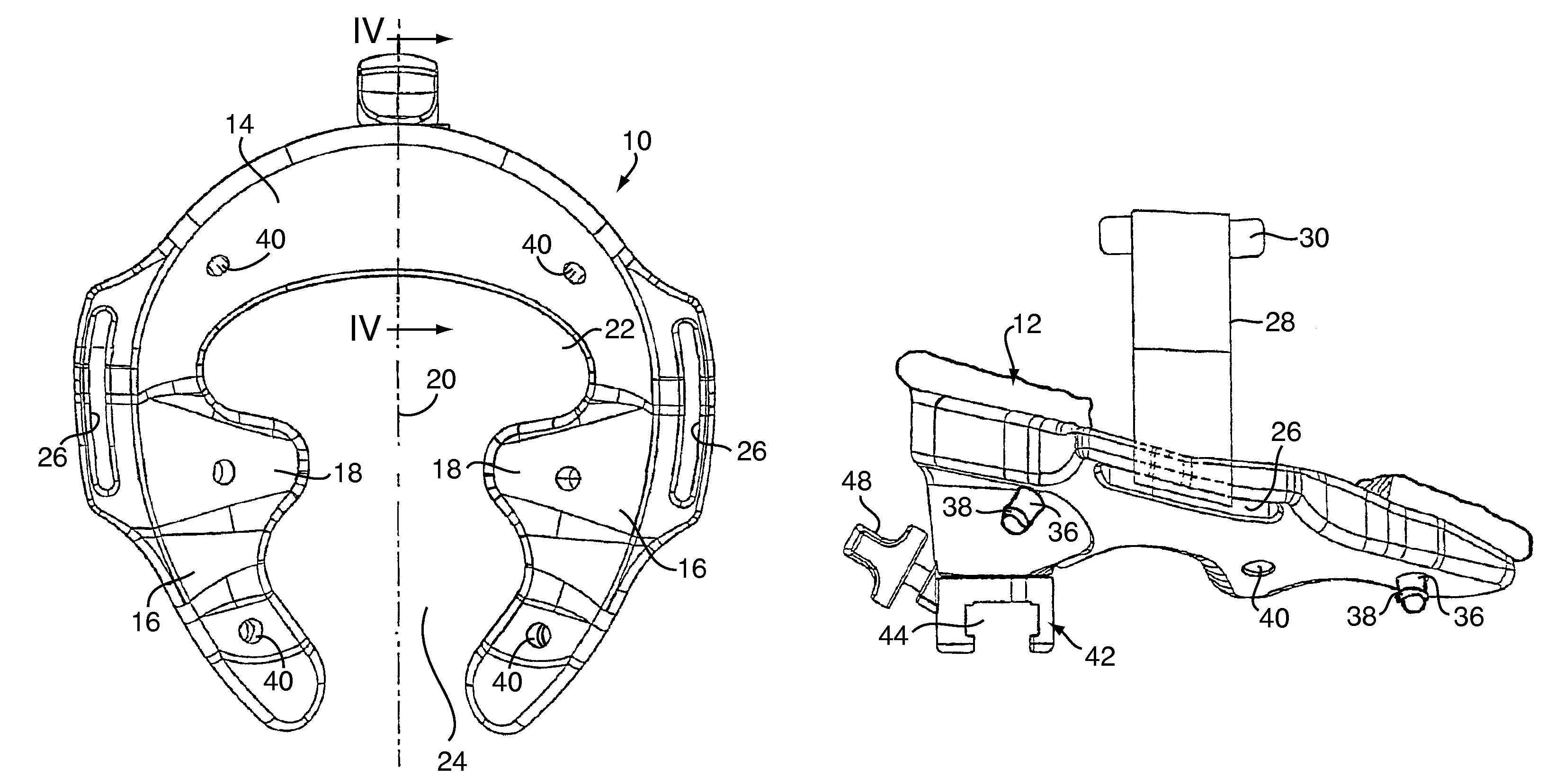
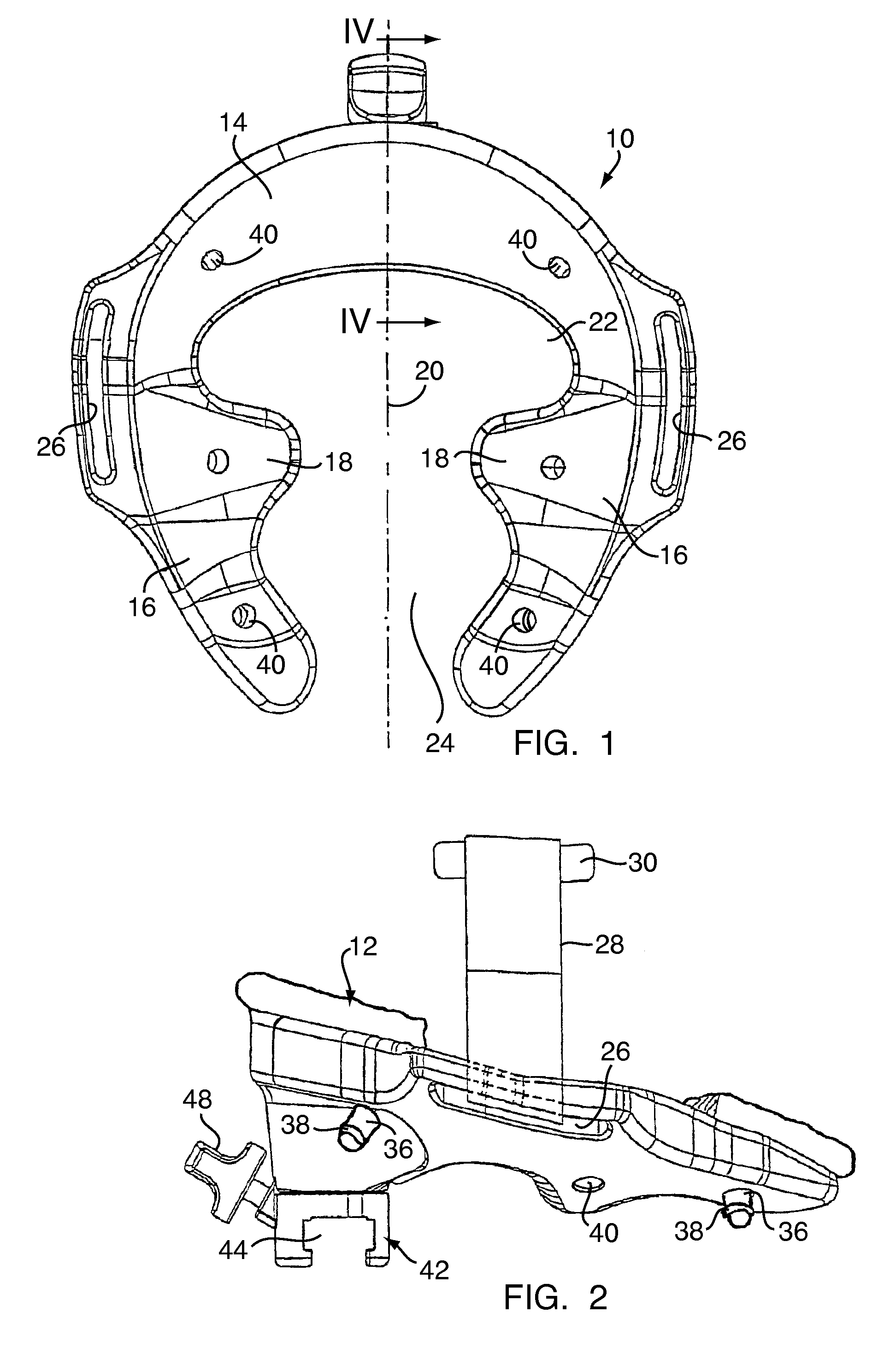
[0012]The headrest of the invention is adapted to the particular shape of the human head and supports the head on suitable surfaces of the skull, namely the rear of the head or the forehead as well as the cheekbones. By way of the spherical shell shape and cylindrical curvature respectively of its sections the head is so bedded that it cannot fall to the side. The cheekbone supports on the side sections make possible on one hand a-good support of the face in the case of the patient lying on his or her stomach, with however the eye parts and the mouth and nose remaining free for inhaling and exhaling as well as for the use of an anesthesia mask or other aids. Because of the anatomically correct shape of the headrest of the invention the weight of the head is distributed in large area fashion over the sections of the headrest so that localized pressures are reduced and thereby even in the case of lengthy operations pressure points on the head, especially on the face, can be avoided.
[0013]In contrast to customary headrests in the case of which for lateral support of the head the cushion must be made very thick, that is the head sinks relatively far into the cushion, in the case of the solution according to the invention because of the anatomical shape of the headrest the support cushion can be made thinner. The rest shell is advantageously made of plastic which not only simplifies its manufacture, for example by injection molding methods, but also simplifies the cleaning of the rest shell in daily use of it.
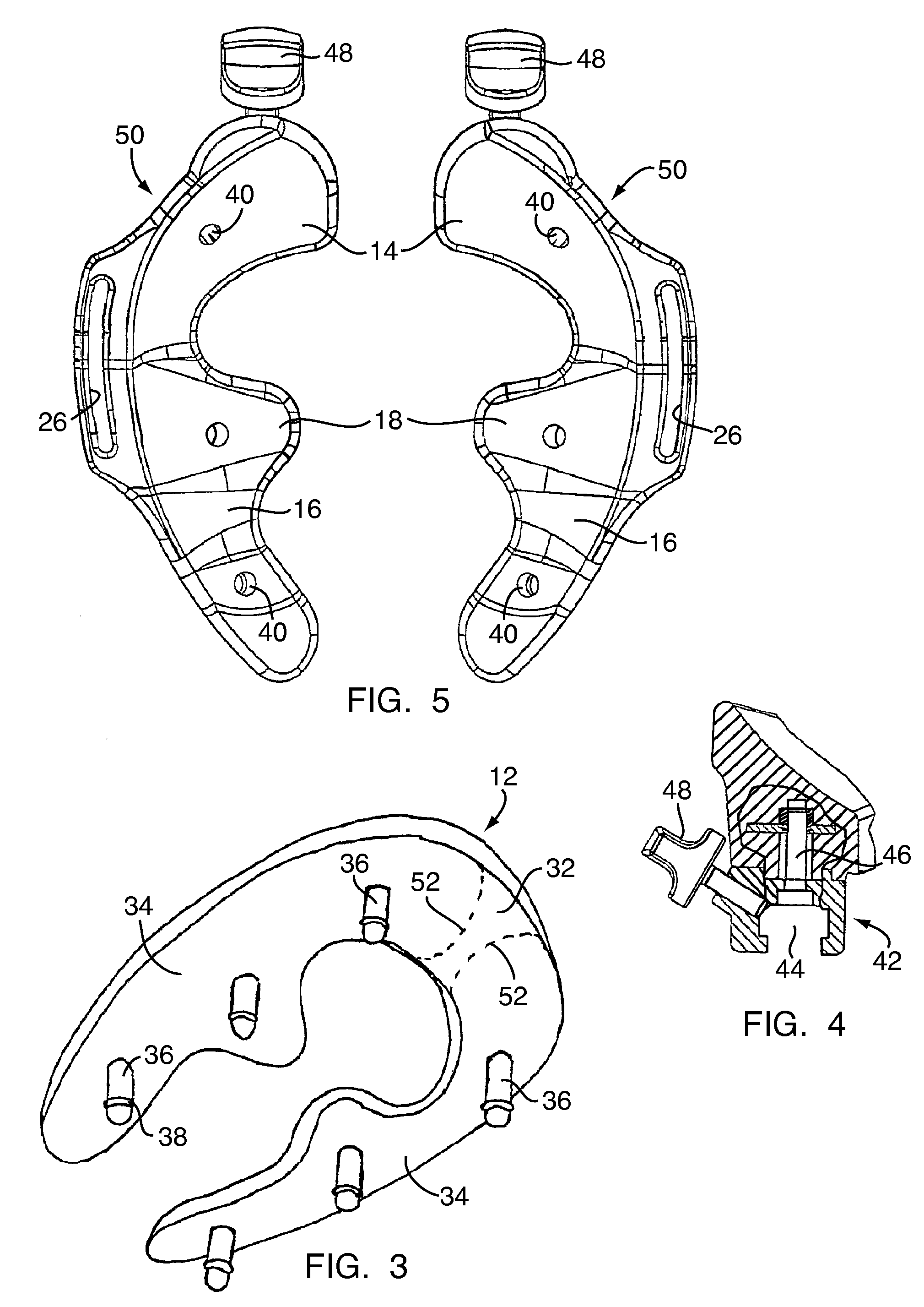
[0014]Preferably the support cushion on its side facing the rest shell has at least two stick pins designed for insertion into through going bores in the rest shell. This way the support cushion can be quickly and securely connected with the rest shell and can be easily again removed from it. Both these bores and also the stickpins can be cleaned simply and without a problem. To avoid an unwanted loosening of the support cushion from the rest shell it can be advantageous if the stick pins on a cylindrical shaft each have an elastically resilient band whose diameter is slightly larger than the diameter of the bores, so that the stick pins can be pressed into and removed from the bores in the rest shell only with a certain resistance.

Problems solved by technology

The headrest is however not well adopted to the shape of human heads and is unsuited to support the head of a patient during an operation where the patient has to be held motionless for a long time and in such a way that the patient is not injured for example by pressure points or the like.

Method used


Image

  • Headrest for a patient-bearing surface
  • Headrest for a patient-bearing surface
  • Headrest for a patient-bearing surface

Examples


Embodiment Construction

[0023]The headrest illustrated in FIGS. 1-4 has an approximately horseshoe-shaped form and includes a rest shell, indicated generally at 10, and a support cushion 12 conforming in its shape to that of the shell. The rest shell has a central section 14 designed to support the rear head of a patient (lying on his or her back) or the forehead of a patient (lying on his or her stomach). This central section 14 on its upper or inner side facing the viewer in FIG. 1 is of at least nearly spherical shell shape. Connected to the central section 14 are two side sections 16 which approach one another with their free ends and each of which has a section 18 protruding toward the other side section 16, which sections 18 form a cheekbone support, that is a support which supports in the region of the cheekbones the face of a patient lying on his or her stomach. The side sections 16 conform approximately to a common cylindrical surface whose axis is parallel to the line of symmetry 20 of the headre...


PUM


Abstract

A headrest for a patient-bearing surface, having an approximately horseshoe-shaped form and comprising a central section (14) for supporting the back of the head or the forehead, the bearing surface thereof being at least approximately spherical shell-shaped, also comprising two side sections (16) which are arranged at a distance from each other and whose bearing surfaces conform at least approximately to a common cylindrical surface whose axis is parallel to a symmetrical line (20) of the headrest extending between the side surfaces (16). A cheekbone support (18), which protrudes in the direction of the other side section (16), is provided on each side section (16).

Description

CROSS REFERENCE TO RELATED APPLICATIONS[0001]Applicants hereby claim foreign priority benefits under 35 U.S.C. 119 of PCT Patent Application No. PCT / EP2003 / 010719 filed Sep. 26, 2003 and German Patent Application No. 202 17 825.0 filed Nov. 18, 2002, the disclosures of which are herein incorporated by reference.BACKGROUND OF THE INVENTION[0002]1. Technical Field[0003]The invention concerns a headrest for a patient-bearing surface, especially that of an operating table.[0004]2. Background Art[0005]A headrest is known from U.S. Pat. No. 6,276,012 B2, which rest consists of a U-shaped part and a plate-shaped section lying between the legs of the U. In the case of a patient lying on his or her back the head of the patient is supported by both of the parts. In the case of the patient lying on his or her stomach the plate-shaped part is swung away so that the head of the patient lies with the forehead on the middle bar of the U, and at least the mouth and nose of the patient lie free. The...

Claims


Application Information

Patent Timeline
Patent Type & Authority Patents(United States)
IPC IPC(8): A61F11/00A42B1/06A61B19/00A61F5/37A61F7/02A61G7/07A61G13/12
CPCA61F5/3707A61G13/12A61B19/203A61F7/007A61F2007/0003A61G7/072A61G13/121A61G2200/325A61G2210/90A61B90/14
Inventor PIONTEK, MANFRED
Owner MAQUET GMBH
Learn More