Shoe having detachable cushioning member

a cushioning member and shoe technology, applied in the direction of wear-resistance attachments, fastenings, heels, etc., can solve the problems of difficult manufacturing of the heel to which the cushioning member is mounted, the structure of the shoe should be modified, and the process for mounting the cushioning member is difficult. , to achieve the effect of simple structure, easy detachable, and easy manufacturing of the cushioning member 100

Inactive Publication Date: 2013-02-05
KOH JONG TAEK
View PDF6 Cites 11 Cited by
  • Summary
  • Abstract
  • Description
  • Claims
  • Application Information

AI Technical Summary

Benefits of technology

[0013]Accordingly, the present invention has an advantage in that the cushioning member 100 and 200 is separately manufactured from a main body of the shoe and the cushioning member 100 and 200 is easily detachable from the heel 11 of the shoe through the attachment by the Velcros 21, 111, and 222, and it is possible to mount the cushioning member 100 and 200 only by forming the seating recess 20 having a simple structure at the heel 11, so that it is possible to simply change the already-established manufacturing equipment of the shoe and it is possible to easily manufacture the cushioning member 100 and 200 because of the simple structure of the cushioning member 100 and 200.
[0014]Further, the cushioning member 100 according to the present invention can be simply assembled or separated by the piston rod 130 so that it is possible to easily replace the spring 140 and the cushioning piece 150. Therefore, it is possible to simply and conveniently adjust the cushioning member 100 to have the desired cushioning degree appropriate for the weight of any person and the user can directly adjust the cushioning degree as well.
[0015]Further, the cushioning member 100 according to the present invention limits the maximum displacement of the spring 140 to make the spring 140 return to its original state through receiving the restoration force from the cushioning piece 150. Therefore, it is possible to use the spring 140 for a long time without the replacement and it is possible to easily replace the worn lower case 120 so that the repair expense of the cushioning member 100 can be advantageously reduced.
[0016]Furthermore, according to the cushioning member 100 of the present invention, the impact is absorbed by the spring 230, the case 210, and the cover 220 so that the impact can be relieved in multiple stages, the spring 230 is fitted around the spring support part 240 to extend the life-span of the spring 230, and the air of the inner space 212 is exhausted and the outside air is introduced to the inner space 212 so that it is possible to achieve the cushioning effect by the air flow. Therefore, if a problem is generated in one cushioning scheme, the cushioning function can be implemented by the remaining cushioning schemes so that it is possible to use the heel 30 for shock absorbing without the replacement of the heel 30.

Problems solved by technology

However, the conventional shoes have the structure in which the cushioning member is mounted to an internal side of an outsole of the shoe, so that it is difficult to manufacture the heel to which the cushioning member is mounted.
Further, the mounting structure is complicated so that the process for mounting the cushioning member is difficult as well.
Because of these difficulties, in order to mount the cushioning member, there is a burden in that the structure of the shoe should be modified and manufacturing equipment according to the modification should be additionally purchased.
Further, when a user desires to replace the cushioning member having the completed life-span due to the long-term use of the conventional shoes, the cushioning member is mounted to the internal side of the outsole so that it is impossible to separately replace only the cushioning member and thus the user should newly purchase the shoes in the end and spend the additional expense for the new shoes.
However, in the conventional shoes according to the prior arts, it is difficult to replace the corresponding components.
Therefore, a problem occurs in that the manufacturing expense of the manufacturer increases and the total stock increases.
Because of the manufacturing expense, the manufacturer cannot manufacture the shoes having the various cushioning degree and thus there occurs a difficulty in that the customer cannot select the shock-absorbing shoes that are appropriate for his / her weight and have the desired cushioning degree.

Method used


Image

  • Shoe having detachable cushioning member
  • Shoe having detachable cushioning member
  • Shoe having detachable cushioning member

Examples


Embodiment Construction

]

[0028]Hereinafter, exemplary embodiments of the present invention will be described with reference to the accompanying drawings for easy implementation by those skilled in the art. In the following description, the same elements will be designated by the same reference numerals although they are shown in different drawings. Further, in the following description, detailed explanation of known related functions and constitutions may be omitted so as to avoid unnecessarily obscuring the subject manner of the present invention.

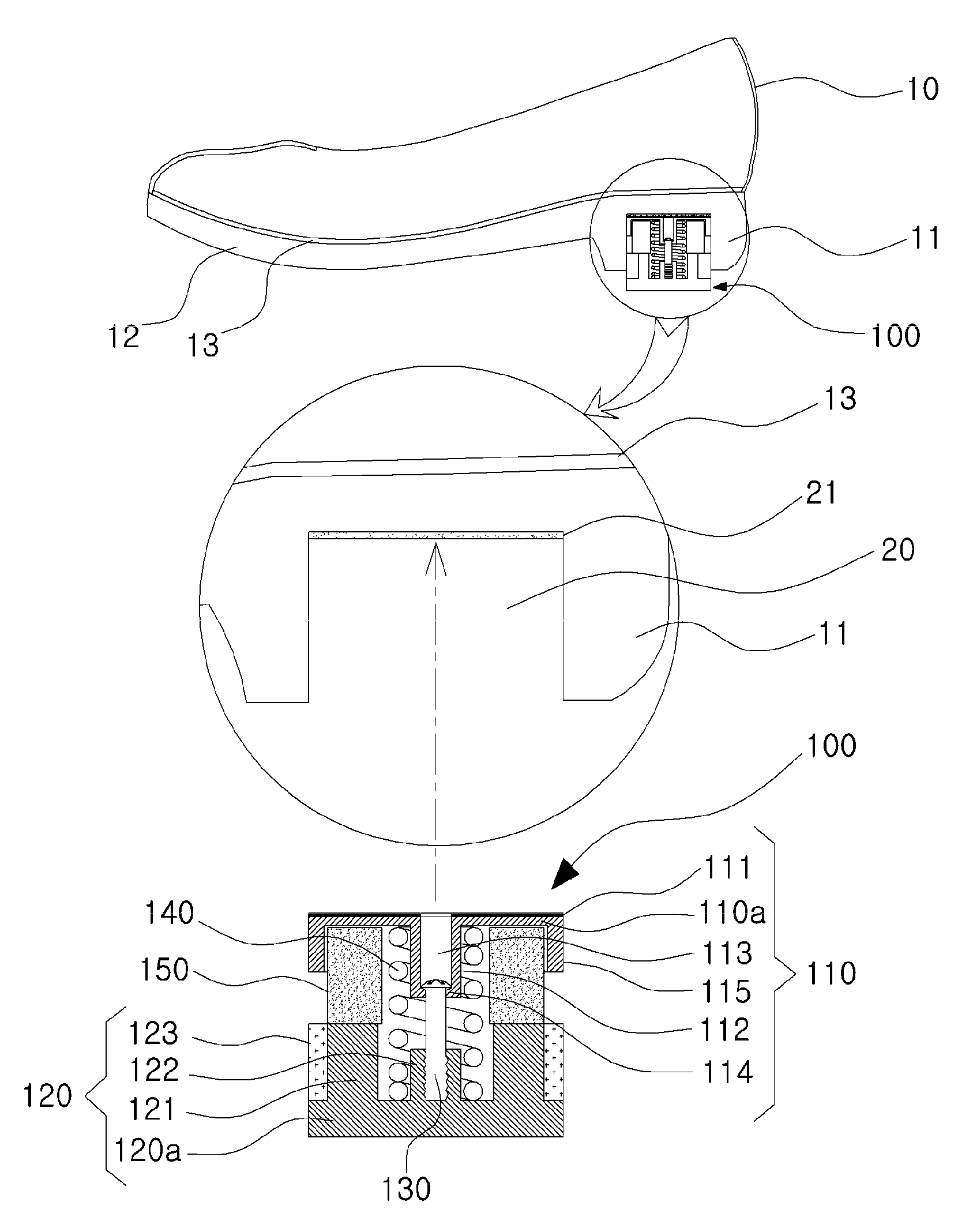
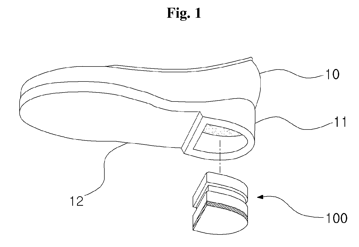
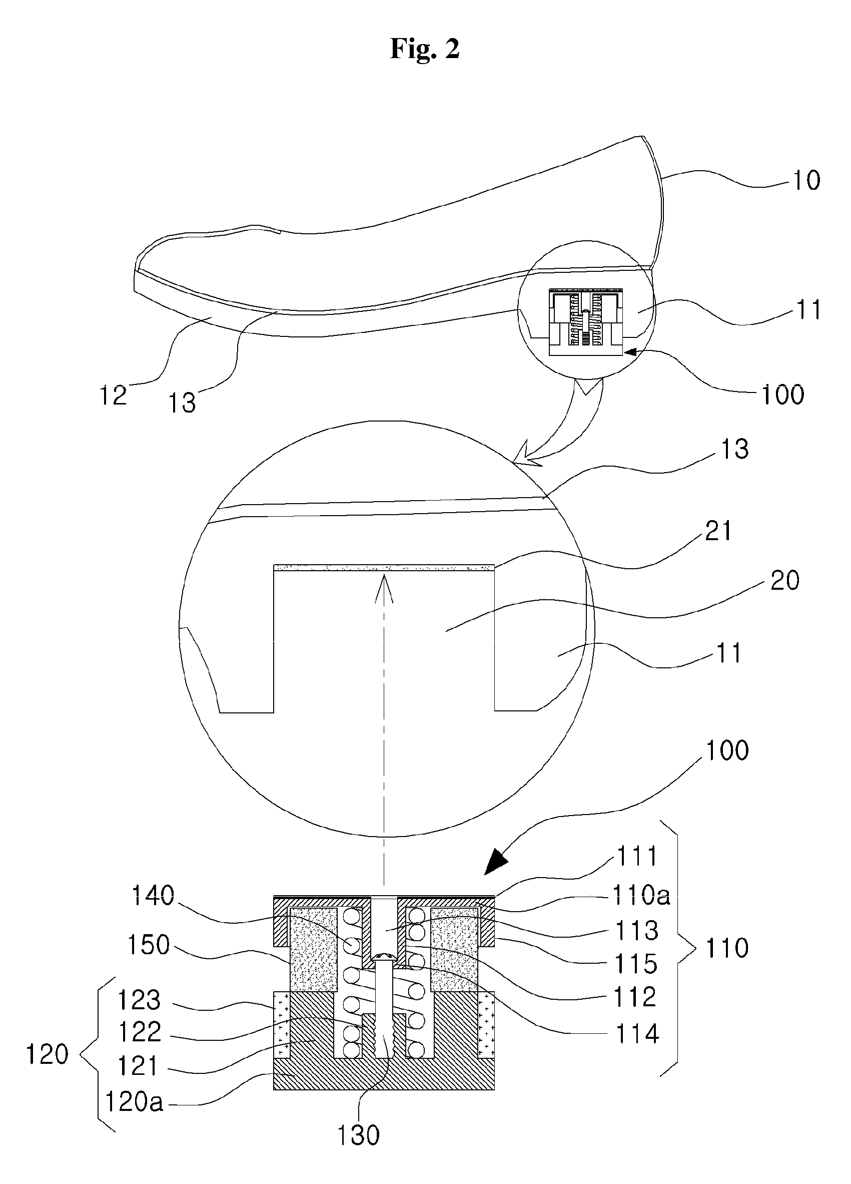
[0029]FIG. 1 is a perspective view illustrating a bottom surface of a shoe including a detachable cushioning member according to an embodiment of the present invention, FIG. 2 is a cross-sectional view illustrating a shoe including a detachable cushioning member according to an embodiment of the present invention and a partial enlarged view illustrating a state where the cushioning member 100 is mounted, FIG. 3 is an exploded perspective view illustrating the det...


PUM

PropertyMeasurementUnit
diameteraaaaaaaaaa
sizeaaaaaaaaaa
distanceaaaaaaaaaa

Abstract

Disclosed is a shoe having a detachable cushioning member, in which the cushioning member for relieving an impact is detachable from a lower surface of a heel. More particularly, in the shoe having a detachable cushioning member, the cushioning member is selectively mounted to a lower surface of a heel of the shoe, a structure of the heel for mounting the cushioning member is simple so that it is possible to easily manufacture the shoe, and only the cushioning member has the construction for cushioning so that it is possible to easily replace and repair the cushioning member.

Description

TECHNICAL FIELD[0001]The present invention relates to a shoe having a detachable cushioning member, in which the cushioning member for relieving an impact is detachable from a lower surface of a heel. More particularly, the present invention relates to a shoe having a detachable cushioning member, in which the cushioning member is selectively mounted to a lower surface of a heel of the shoe, a structure of the heel for mounting the cushioning member is simple so that it is possible to easily manufacture the shoe, it is possible to easily change the cushioning degree of the cushioning member, and it is possible to easily repair the cushioning member.BACKGROUND ART[0002]In the conventional shoe having a cushioning member in an outsole, a cushioning member can reduce an impact applied to the ankle or knee during walking while wearing the shoe so that it is possible to protect the ankle or knee.[0003]The conventional shoes having such a function are disclosed in Korean Utility Model Reg...

Claims


Application Information

Patent Timeline
Patent Type & Authority Patents(United States)
IPC IPC(8): A43B21/26
CPCA43B3/0047A43B21/30A43B21/32A43B21/54
Inventor KOH, JONG TAEK
Owner KOH JONG TAEK
Why Eureka
Try Eureka