Multi-receiver heliostat system architecture

a heliostat and multi-receiver technology, applied in the field of solar energy collection devices, can solve the problems of limited land use, achieve the effect of improving the utilization of individual heliostats and land, reducing costs, and increasing the efficiency of heliostats

Active Publication Date: 2013-02-05
ANGELES TECH
View PDF13 Cites 4 Cited by
  • Summary
  • Abstract
  • Description
  • Claims
  • Application Information

AI Technical Summary

Benefits of technology

[0021]The present invention is directed to the architecture of concentrated solar power (CSP) systems utilizing heliostats and methods for controlling fields of heliostats in concentrated solar power systems to improve the utilization of individual heliostats and the utilization of land required by heliostat fields. The approach is similar to the central receiver architecture, but has features that reduce cost by increasing the efficiency of heliostats, by allowing denser packing of heliostats (sun-tracking reflector assemblies), and by supporting substantial flexibility in sizing and siting to reduce development risk. The present invention is expected to substantially reduce the development, deployment, and operations and maintenance costs of the heliostat field, and to reduce the land-use footprint required for such plants. Land use becomes limited by providing open areas required for construction and maintenance access.
[0022]The apparatus and method of the present invention allows each heliostat in a solar energy collection system configured from a plurality of heliostats and receivers to be dynamically targeted to a plurality of acceptable receiver locations over time. The architecture of the present invention is contrasted with prior art systems, wherein each heliostat is statically and permanently assigned to direct incident solar radiation to a single central receiver positioned at a fixed receiving location. The present invention discloses a method of dynamic retargeting of heliostats in a field and discloses how the retargeting method of the present invention can provide the ability to reduce cosine, shadowing, blockage and other losses and / or reduce the range of motion required by each heliostat.
[0023]The dynamic retargeting of heliostats to various receiver locations provides operational flexibility to:
[0024](1) Perform maintenance on a receiver without losing all the power-collection capability of some large group of heliostats (for example, losing the utility of all heliostats associated with a single receiver if each heliostat were statically assigned to one specific receiver);
[0027]In an embodiment of the present invention, any static physical or geometrical relationship between collecting / focusing elements (heliostats) and receivers is removed. The most generic layout would be a large number of heliostats arranged in a uniform rectilinear grid pattern or a triangular grid pattern. This approach is not used in prior art systems because under the assumption of a single receiver being associated with a given heliostat field, it is more cost-effective to use a radial stagger pattern to optimize the heliostat field layout to avoid self-shadowing and blockage by the heliostats.
[0028]A system with a relatively dense layout of heliostats in a decoupled, uncommitted design provides various additional advantages. In such a system, without fundamentally changing the layout of the heliostat field:

Problems solved by technology

Land use becomes limited by providing open areas required for construction and maintenance access.

Method used


Image

  • Multi-receiver heliostat system architecture
  • Multi-receiver heliostat system architecture
  • Multi-receiver heliostat system architecture

Examples


Embodiment Construction

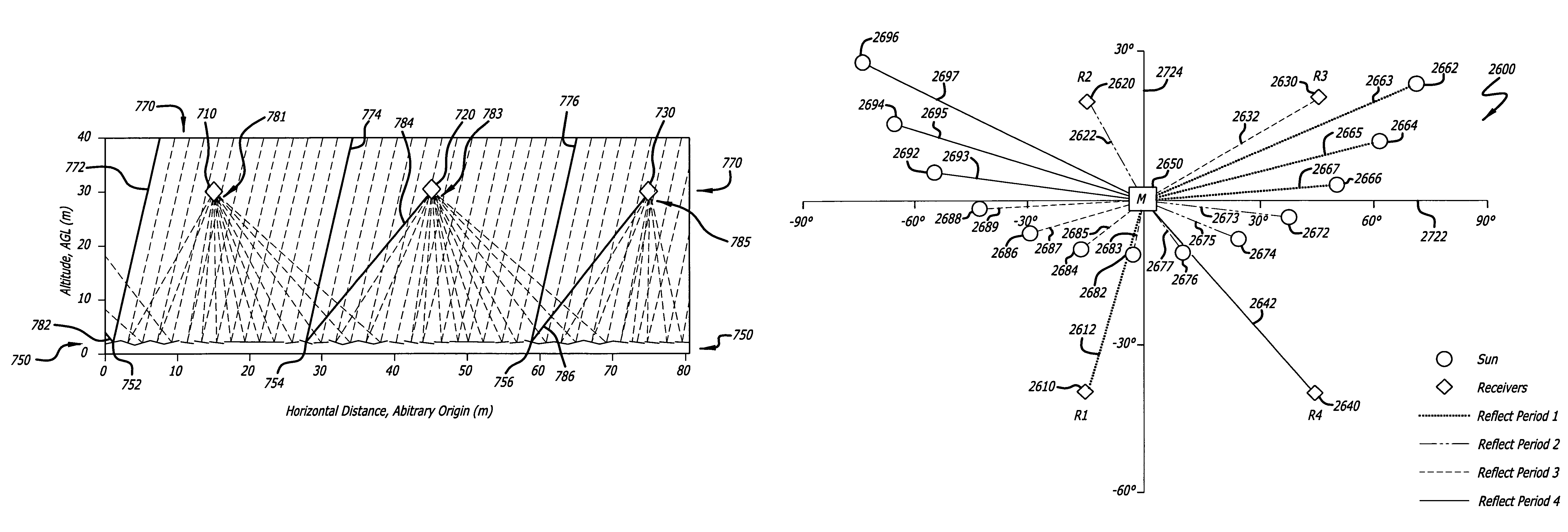
[0070]The subject invention improves the utilization of heliostats (sun-tracking reflector assemblies), simplifies the design of heliostats, and allows better land utilization by heliostat fields used for concentrated solar power generation (CSP) systems. The systems and methods of the present invention improve upon the conventional central receiver architecture, having features that reduce cost by increasing the efficiency of heliostats, by allowing denser packing of heliostats, and by supporting substantial flexibility in sizing and siting to reduce development risk.

[0071]By way of definition, the term “receiver” is used herein to refer to a device for capturing incident radiation and converting such incident radiation into another form of energy. The term “receiving location” is used herein to refer to the common location to which solar radiation is directed by a plurality of heliostats. A receiver may be placed at the receiving location; however, the receiving location may alter...


PUM


Abstract

A system architecture for large concentrated solar power applications that increases heliostat utilization efficiency and land utilization efficiency is described. Embodiments of the invention include a large heliostat field in which are distributed a number of receiving locations, and wherein there is the assignment of heliostats to receiving locations is dynamic. Embodiments of the invention include dynamically targeting heliostats to receiving locations wherein the target determination process is performed frequently during operation and wherein such dynamic targeting can be utilized to various ends. Embodiments of the invention include configurations wherein cosine losses associated with heliostat pointing are significantly reduced, wherein heliostats may be closely packed without incurring substantial shadowing and blocking losses thereby significantly increasing land utilization, and wherein other benefits are realized.

Description

BACKGROUND OF THE INVENTION[0001]The present invention is directed to solar energy collection devices, and more particularly to a system and method for controlling a field of heliostats used to direct solar energy to a plurality of receivers for power generation.[0002]Various technologies have been explored, developed, and implemented for generating electricity from solar energy. The two principal technologies for converting solar energy into electricity are photovoltaic and thermal means. Photovoltaic “solar cells” convert incoming photons directly into electricity using the photoelectric effect, for example using semiconductors based on silicon (Si) or gallium-arsenide (GaAs). Thermal conversion captures broadband solar radiation in a heat transfer medium (for example, oil, water, or air) and then uses a traditional steam or gas turbine to spin a generator. The simplest systems mount solar energy collectors in a manner that fixes their orientation with respect to the surface of th...

Claims


Application Information

Patent Timeline
Patent Type & Authority Patents(United States)
IPC IPC(8): F24J2/46F24S50/20
CPCF24J2/07F24J2/5431Y02E10/41Y02E10/47F24J2/16F24J2/542F24J2002/0084F24J2002/1076F24S20/20F24S23/77F24S30/452F24S30/48F24S2020/16F24S2023/87Y02E10/40
Inventor CALDWELL, DOUGLAS W.
Owner ANGELES TECH
Why Eureka
Try Eureka