Fixing device for rotary blade

a fixing device and rotary blade technology, applied in the direction of threaded fasteners, screws, fastening means, etc., can solve the problem of not divulging a technique for tightening, and achieve the effect of sufficient cutting depth of the saw blad

Inactive Publication Date: 2013-02-05
MAKITA CORP
View PDF29 Cites 4 Cited by
  • Summary
  • Abstract
  • Description
  • Claims
  • Application Information

AI Technical Summary

Benefits of technology

[0009]According to a first aspect of the invention, the operating lever is provided without increase in size of the screw body with respect to its radial direction and thickness direction, and therefore, when it is applied to an existing portable circular saw, a sufficient

Problems solved by technology

However, though a fixing screw described in U.S. Pat. No. 6,843,627 is characterized document does not disclose a technique for tightening it firmly.
Though this fixing nut can be tightened and loo

Method used


Image

  • Fixing device for rotary blade
  • Fixing device for rotary blade
  • Fixing device for rotary blade

Examples


Embodiment Construction

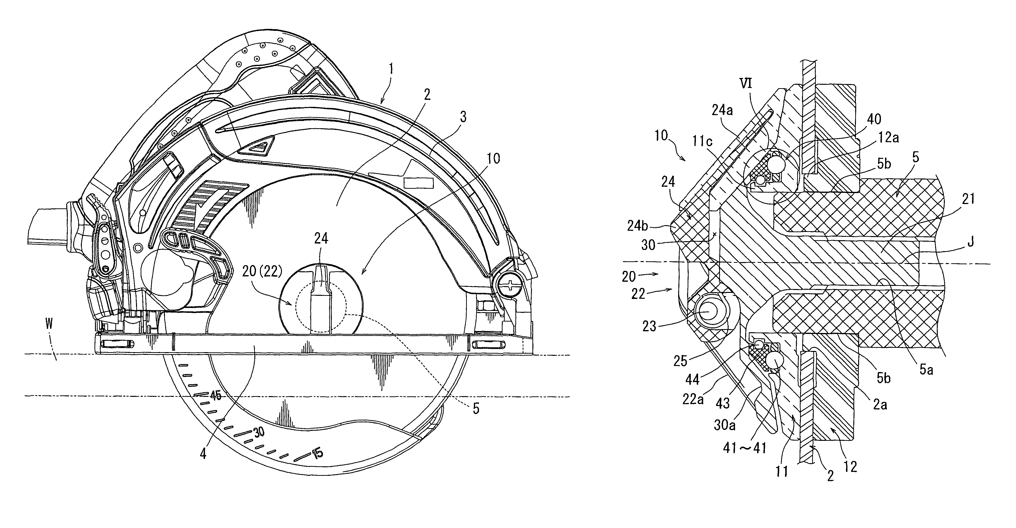
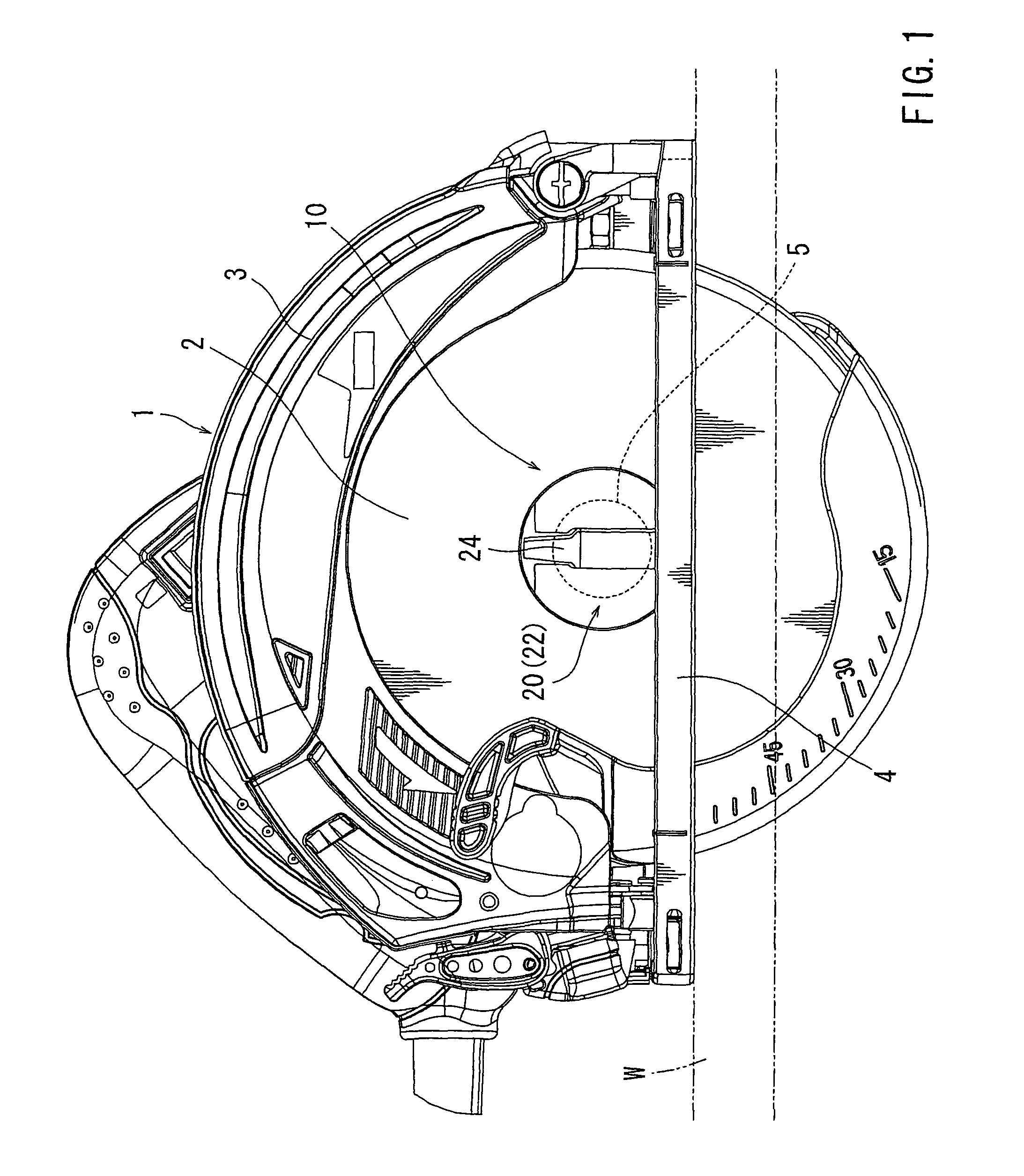
[0030]Next, an embodiment of the present invention will be described with reference to FIGS. 1 to 8. FIG. 1 shows a portable circular saw 1 with a circular saw blade 2 fixed by using a fixing device 10 of this embodiment. The present embodiment exemplifies the portable circular saw 1 as an example of rotary tools, and the circular saw blade 2 as an example of rotary blades. The constitution of the portable circular saw 1 itself is similar to that known in the prior art and requires no particular modification in the present embodiment. The periphery of an upper half circumference of the saw blade 2 is covered with a blade case 3. A driving motor and a speed-reducing mechanism is located at the backside of this blade case 3. An output of this driving motor is transmitted via the speed-reducing mechanism into a spindle 5 protruding into the blade case. In order to fix the saw blade 2 to this spindle 5, the fixing device 10 is used as described below.

[0031]Symbol 4 in FIG. 1 designates ...


PUM


Abstract

A saw blade fixing device is constructed so that a screw flange of a screw body tightened into a screw hole of a spindle is made to have a truncated cone shape, an operating lever is provided to be operable to pivot to a received position and a use position by reversing the operating lever between front and back sides, and this operating lever does not protrude from the truncated cone shape when it is received.

Description

BACKGROUND OF THE INVENTION[0001]1. Field of the Invention[0002]The present invention relates to a fixing device (tool-less blade clamp) for fixing a rotary blade such as a saw blade to a spindle without the use of a special tool in a rotary tool such as, for example, a portable circular saw.[0003]2. Description of the Related Art[0004]Conventionally, as a technique relating to this kind of fixing devices, for example, a tool-less blade clamp assembly (fixing screw) which can be manually loosened without using a tool by utilizing a ratchet mechanism in order to prevent over-tightening is described in U.S. Pat. No. 6,843,627.[0005]In addition, in Japanese Laid-Open Patent Publication No. 2001-520734, a retractable lever is provided in a fixing nut tightened to a threaded shaft part of a spindle, and the fixing nut can be tightened to the threaded shaft part of the spindle with a large torque while this lever is grasped, thereby enabling a user to firmly fix a rotary blade to the spin...

Claims


Application Information

Patent Timeline
IPC IPC(8): F16B35/06
CPCB27B5/32
Inventor HIRABAYASHI, SHINJIKOJIMA, NAOYUKI
Owner MAKITA CORP
Why Eureka
Try Eureka