Multipurpose rotary device and generating system including same
a rotary device and multi-purpose technology, applied in wind motors with solar radiation, renewable energy generation, greenhouse gas reduction, etc., can solve the problems of large investment cost, destruction of ecosystem, and infinite field to be improved, and achieve high efficiency, large rotational force, and clean electrical energy
- Summary
- Abstract
- Description
- Claims
- Application Information
AI Technical Summary
Benefits of technology
Problems solved by technology
Method used
Image
Examples
first embodiment
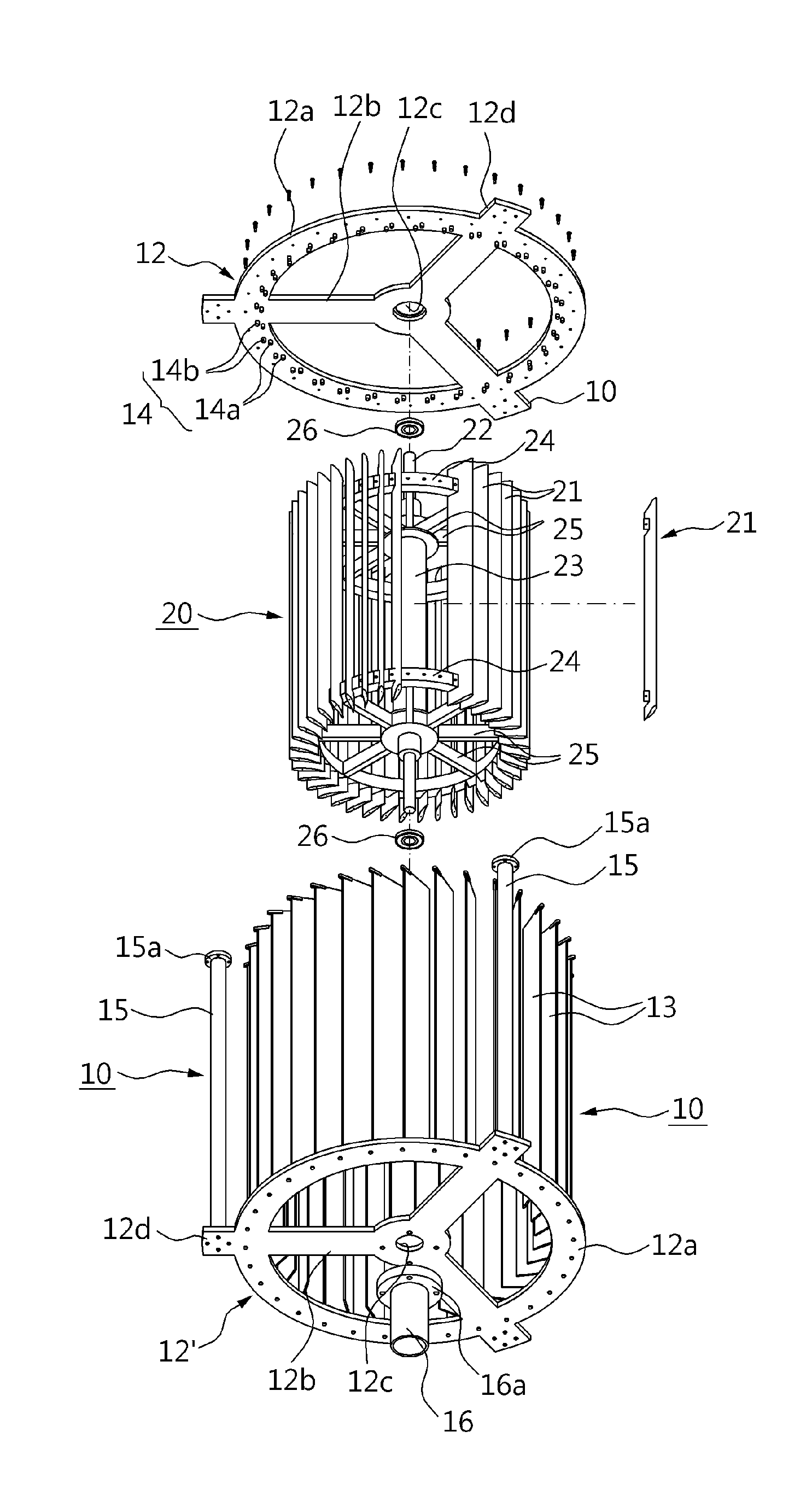
[0051]Referring to FIG. 2a to FIG. 2f, the multipurpose rotary device 1R according to the present invention is a device configured such that a stable unidirectional rotational force (rotational moment) with high efficiency in an even and uneven load or an irregular load, in which the position is remarkably changed, that is obtained from nature such as water power, wave power, tidal power, and wind power can be acquired irrespective of a load inflow direction, and includes a load guide body 10 and a rotor 20.
[0052]The load guide body 10 includes an upper support member 12 and a lower support member 12′ that are disposed to face each other at the upper and lower sides thereof and connected to one another such that the rotor 20 is rotatably installed, and a plurality of load guide plates 13 that are disposed in a longitudinal direction configured such that a circle is formed between the upper and lower support members 12 and 12′ to correspond to blades 21 of the rotor 20.
[0053]The uppe...
second embodiment
[0073]Referring to FIG. 3a to FIG. 3e, the multipurpose rotary device 1R according to the present invention includes the load guide body 10 and the rotor 20, and includes the upper support member 12 and the lower support member 12′ in which the load guide body 10 is disposed to face and connected to each other at the upper and lower sides such that the rotor is rotatably installed, the plurality of load guide plates 13 rotatably installed in a longitudinal direction between the upper and lower support members 12 and 12′ to correspond to the blades 21 of the rotor 20, and the stop pins 14 formed in the facing inner side of the upper and lower support members 12 and 12′ and configured to control the rotational angle of the load guide plates 13.
[0074]Since the upper support member 12 and the lower support member 12′ are coupled to correspond to each other, the upper support member 12 and the lower support member 12′ are formed in the same or similar form and include the annular rings 1...
third embodiment
[0085]Referring to FIG. 4a to FIG. 4g, the multipurpose rotary device 1R according to the present invention includes load guide body 10 and a rotor 20, and further includes load adjustment opening and closing means 30 configured to adjust a loading amount of fluids guided to the load guide body 10 by the rotor 20 or block the loads of the guided fluids.
[0086]The load adjustment opening and closing means 30 includes a pair of fastening pieces 31a and 31b such that a rotation space in which the upper and lower sides of the load guide plates 13 are inserted and rotated is defined, and includes a plurality of rotational members 31 rotatably installed between inside and outside stop pins 14a and 14b, rotational chain gears 32 connected to the load guide plates 13 and the rotational members 31, a rotational chain 33 configured to rotate the rotational chain gears 32, and an opening and closing means driving unit 34 configured to transmit power to rotate the rotational chain 33.
[0087]The o...
PUM
 Abstract
Description
Claims
Application Information
 - R&D
- Intellectual Property
- Life Sciences
- Materials
- Tech Scout
- Unparalleled Data Quality
- Higher Quality Content
- 60% Fewer Hallucinations
Browse by: Latest US Patents, China's latest patents, Technical Efficacy Thesaurus, Application Domain, Technology Topic, Popular Technical Reports.
© 2025 PatSnap. All rights reserved.Legal|Privacy policy|Modern Slavery Act Transparency Statement|Sitemap|About US| Contact US: help@patsnap.com


