
Multipurpose rotary device and generating system including same

a rotary device and multi-purpose technology, applied in wind motors with solar radiation, renewable energy generation, greenhouse gas reduction, etc., can solve the problems of large investment cost, destruction of ecosystem, and infinite field to be improved, and achieve high efficiency, large rotational force, and clean electrical energy

Active Publication Date: 2014-02-13
BAE MYUNG SOON
View PDF10 Cites 23 Cited by
  • Summary
  • Abstract
  • Description
  • Claims
  • Application Information

AI Technical Summary

Benefits of technology

The present invention provides a multipurpose rotary device that can effectively guide and convert various fluid loads, such as wave, tidal, and wind power, into clean electrical energy. The device has a non-conductive guide body that can handle uneven and rough loads, while still generating a large rotational force. The device also has versatility in blading and capacity adjustment, making it suitable for different environments and applications. Additionally, the device can be used as an offshore generating system with a lighthouse chamber that facilitates easy movement and stable installation. Overall, the invention provides a high-power, efficient, and versatile rotary device for generating and converting various fluid loads into electrical energy.

Problems solved by technology

Clean energy using such devices is effectively utilized all over the world, but it can be seen that the fields to be improved are infinite.
However, as problems in the researches using tidal power, there are problems such as difficulties caused due to the load directions and the heights of the loads to be varied and a huge amount of investment costs as well as construction of the method of constructing the bay.
However, due to various technical difficulties such as difficulties of structure installation in the remarkably changed sea, the researches on the generation technology currently remain still in a trial stage.
In addition, the water power generation has been utilized for a long time, but due to difficulties such as limitation of the additional water power generation construction place and a huge amount of costs, in recent times, small hydropower plants and ultra-small hydropower plants that construct by closing stank in the river or streams is developed.
However, a method of blocking a waterway has the environmental issues leading to destruction in ecosystem such as blocking the movement of the fish.
However, as the biggest problem, there is limitation of an installation place that has excellent wind quality, which is continuously blown in a certain direction, because the rotation direction may be changed depending on the direction of the wind.
There is a problem in which a heavy generator is installed at a pillar of a high position.
Therefore, there are difficulties in which costly installation costs due to the devices used to compensate for the problems are required.
In addition, in a case of the vertical axis wind power generating device that is not affected by the direction of the wind, there is a problem in which the loads of action and reaction are exerted to the loads that are exerted in all direction based on the central axis to decrease efficiency thereof.
However, the vertical axis wind power generating device has the structure with low efficiency and is in the real state having difficulties in the large-scale generating.
However, in a case of an auxiliary device configured to guide the wind to a device using a drag in a rotation manner, as the scale of the device is larger, there is a problem in which the rapid response for a wind direction is not efficient at a place in which the wind direction is frequently varied, and the fact in which the structure and the configuration for wind guide vanes and internal blades is not efficient, and thus is not practical.
However, substantially, when the difference in loads is remarkable or during high-speed rotation, it is difficult to respond effectively and rapidly.
Therefore, the higher efficiency is not obtained.
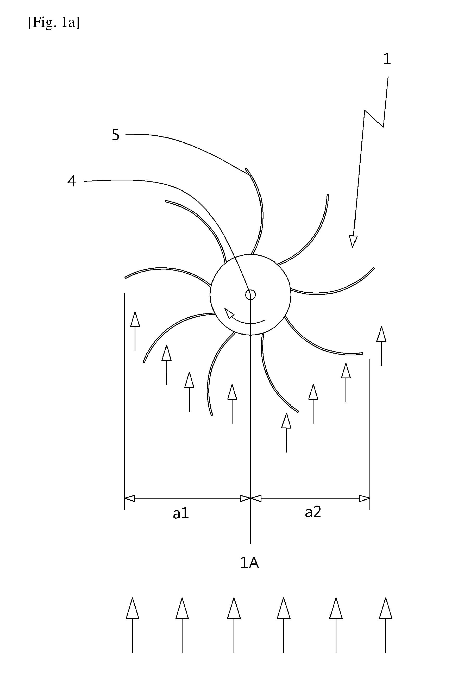
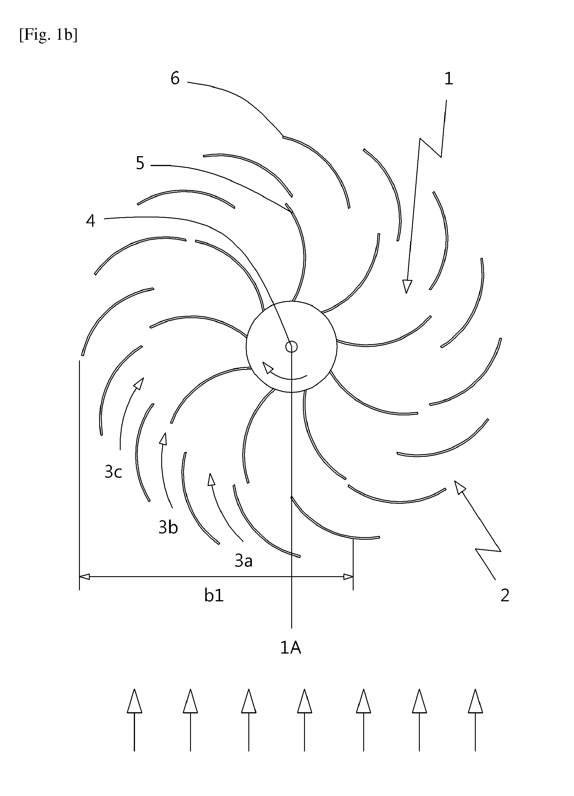
Therefore, there is a problem in which only a minute rotational force corresponding to efficiency obtained due to a curve shape of blades 5 is obtained from a rotor 1.
However, from the viewpoint of a structure of the blades 6a of the rotor 1, the loads that are guided to a portion ‘c2’ located far away from a center output shaft 4 generate a large rotational force, but the portion ‘c1’ is located at a short distance from the output shaft 4, and has limitation in which, from the viewpoint of a structure of the blades 6a of the rotor 1, it is difficult to obtain a large rotational force.

Method used


Image

  • Multipurpose rotary device and generating system including same
  • Multipurpose rotary device and generating system including same
  • Multipurpose rotary device and generating system including same

Examples


first embodiment

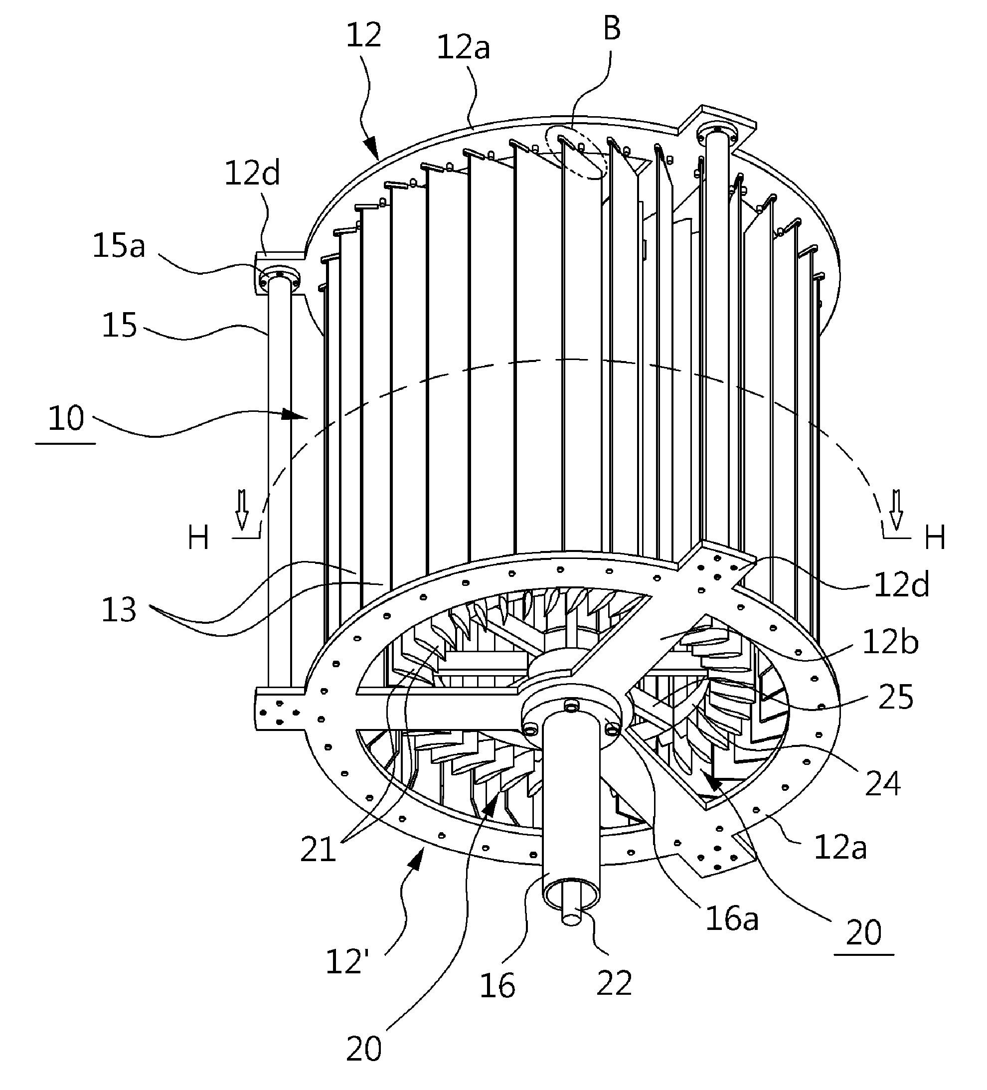
[0051]Referring to FIG. 2a to FIG. 2f, the multipurpose rotary device 1R according to the present invention is a device configured such that a stable unidirectional rotational force (rotational moment) with high efficiency in an even and uneven load or an irregular load, in which the position is remarkably changed, that is obtained from nature such as water power, wave power, tidal power, and wind power can be acquired irrespective of a load inflow direction, and includes a load guide body 10 and a rotor 20.

[0052]The load guide body 10 includes an upper support member 12 and a lower support member 12′ that are disposed to face each other at the upper and lower sides thereof and connected to one another such that the rotor 20 is rotatably installed, and a plurality of load guide plates 13 that are disposed in a longitudinal direction configured such that a circle is formed between the upper and lower support members 12 and 12′ to correspond to blades 21 of the rotor 20.

[0053]The uppe...

second embodiment

[0073]Referring to FIG. 3a to FIG. 3e, the multipurpose rotary device 1R according to the present invention includes the load guide body 10 and the rotor 20, and includes the upper support member 12 and the lower support member 12′ in which the load guide body 10 is disposed to face and connected to each other at the upper and lower sides such that the rotor is rotatably installed, the plurality of load guide plates 13 rotatably installed in a longitudinal direction between the upper and lower support members 12 and 12′ to correspond to the blades 21 of the rotor 20, and the stop pins 14 formed in the facing inner side of the upper and lower support members 12 and 12′ and configured to control the rotational angle of the load guide plates 13.

[0074]Since the upper support member 12 and the lower support member 12′ are coupled to correspond to each other, the upper support member 12 and the lower support member 12′ are formed in the same or similar form and include the annular rings 1...

third embodiment

[0085]Referring to FIG. 4a to FIG. 4g, the multipurpose rotary device 1R according to the present invention includes load guide body 10 and a rotor 20, and further includes load adjustment opening and closing means 30 configured to adjust a loading amount of fluids guided to the load guide body 10 by the rotor 20 or block the loads of the guided fluids.

[0086]The load adjustment opening and closing means 30 includes a pair of fastening pieces 31a and 31b such that a rotation space in which the upper and lower sides of the load guide plates 13 are inserted and rotated is defined, and includes a plurality of rotational members 31 rotatably installed between inside and outside stop pins 14a and 14b, rotational chain gears 32 connected to the load guide plates 13 and the rotational members 31, a rotational chain 33 configured to rotate the rotational chain gears 32, and an opening and closing means driving unit 34 configured to transmit power to rotate the rotational chain 33.

[0087]The o...


PUM


Abstract

A multipurpose rotary device includes a rotor configured to include a plurality of blades in a circumferential direction; and a load guide body configured to guide a flow of fluids flowing into the inside of the rotor, wherein the load guide body includes an upper support member and a lower support member configured to be disposed to face each other at the upper and lower sides thereof and connected to one another such that the rotor is rotatably installed; load guide plates configured to correspond to the blades and are rotatably installed between the upper and lower support members in a longitudinal direction; and stop pins configured to be formed on inner surfaces facing the upper and lower support members to control a rotational angle of the load guide plates.

Description

TECHNICAL FIELD[0001]The present invention relates to a multipurpose rotary device and a generating system including the same, and more particularly, to a multipurpose rotary device configured to guide effectively even or uneven and remarkably rugged loads that are obtained from flow energy of the various fluids generated in the ground, streams, the sea, and the like to maximize rotational efficiency, and thereby generating clean energy with high efficiency, without harming the global environment, and a generating system including the same.BACKGROUND ART[0002]At the present day, as pre-existing fossil energy resources are gradually exhausted and environmental issues come to the fore, the researches that want to use effectively clean alternative energy, in particular, the loads obtained from water power, tidal power, wave power, and the like and the loads caused due to wind power have been actively conducted from a long time ago.[0003]As representative method and devices, there are t...

Claims


Application Information

Patent Timeline
IPC IPC(8): F03B3/18
CPCF03B3/183F03B17/063F03D3/0409F05B2240/121F05B2240/244Y02B10/10Y02B10/30Y02E10/30Y02E10/50Y02E10/728Y02E10/74F03B3/12F03B11/06F03B11/08F03B17/06F03B3/18F03D3/0418F03D9/007F03D13/20H02S10/12Y02E10/20
Inventor BAE, MYUNG-SOON
Owner BAE MYUNG SOON
Learn More