
Recoil starter

a starter and coil technology, applied in the direction of engine starters, muscle operated starters, machines/engines, etc., can solve the problems of increased size of the recoil starter, impaired durability of the damper spring, and impaired durability of the components, so as to reduce the size of the starter and increase the rotational force. , the effect of miniaturizing and lightening

Active Publication Date: 2006-08-22
STARTING IND CO LTD
View PDF15 Cites 16 Cited by
  • Summary
  • Abstract
  • Description
  • Claims
  • Application Information

AI Technical Summary

Benefits of technology

The invention is a recoil starter that solves problems of conventional art by accumulating a large rotational force without damaging components made of plastic material and being miniaturized and lightened. It includes a rope reel, recoil spring, cam, rotary member, bosses, and damper spring. The damper spring is formed with a section shape that allows for a wide area of tight winding around the bosses. The ends of the damper spring are radially movable and elastically deformed by starting resistance of the engine. The bosses on the rope reel and cam have end faces that butt against each other in a middle position of a wound portion of the damper spring. The technical effects of the invention are improved starting performance of the engine and reduced damage to components.

Problems solved by technology

Therefore, the cam is pressed in the axial direction to increase the rotational resistance, or a part of the damper spring is irregularly deformed, so that the durability of the damper spring is impaired.
When the damper spring having a circular section shape is strongly tightly wound around outer peripheral faces of such components, therefore, the outer peripheral faces of the components are deformed because the contact areas between the spring and the components are narrow, thereby causing another problem in that the durabilities of the components are impaired.
However, this countermeasure involves a problem in that the total length of the damper spring is prolonged, and the size of the recoil starter is increased, with the result that it is impossible to miniaturize the recoil starter.

Method used


Image

  • Recoil starter
  • Recoil starter
  • Recoil starter

Examples


Embodiment Construction

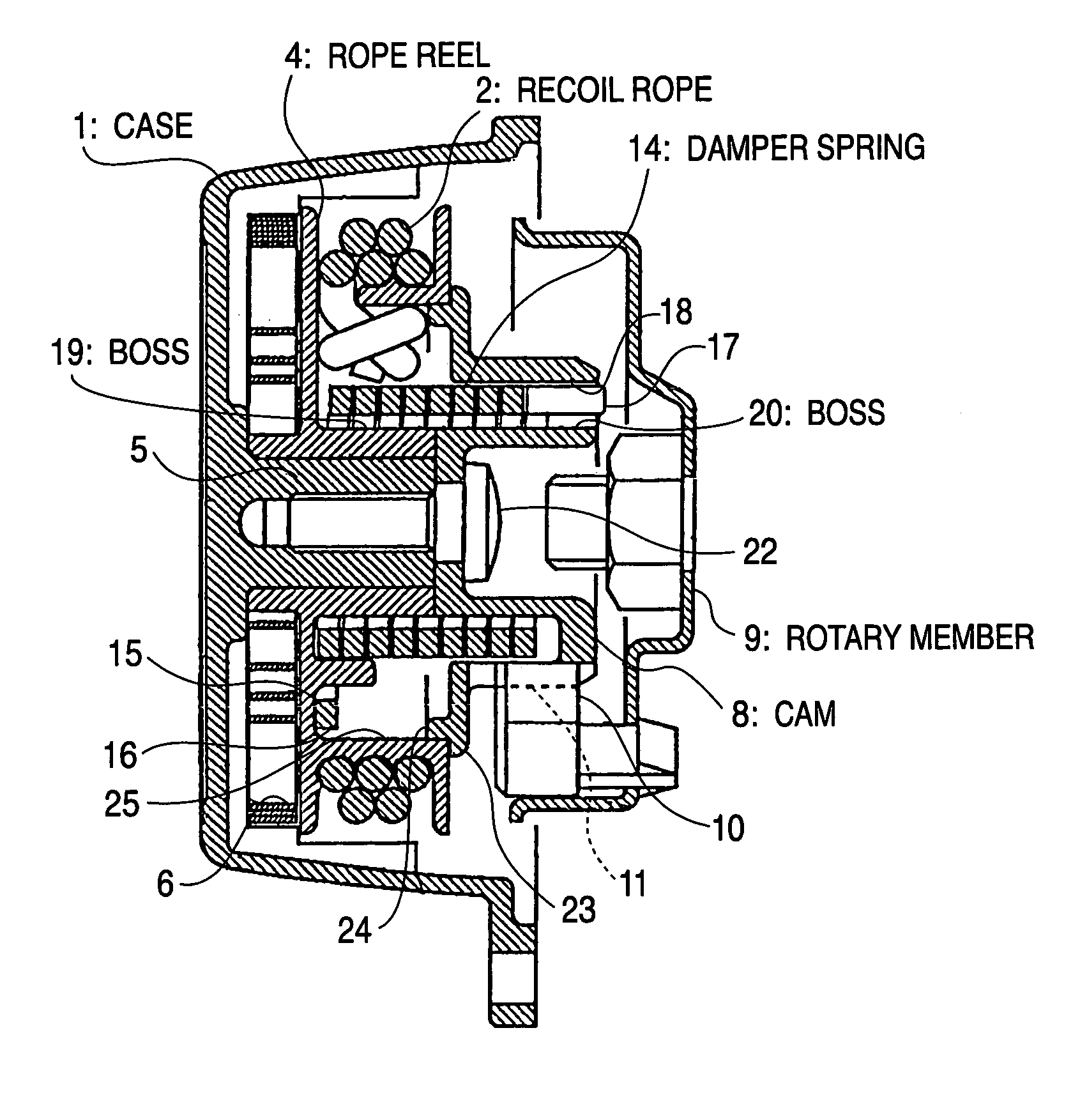
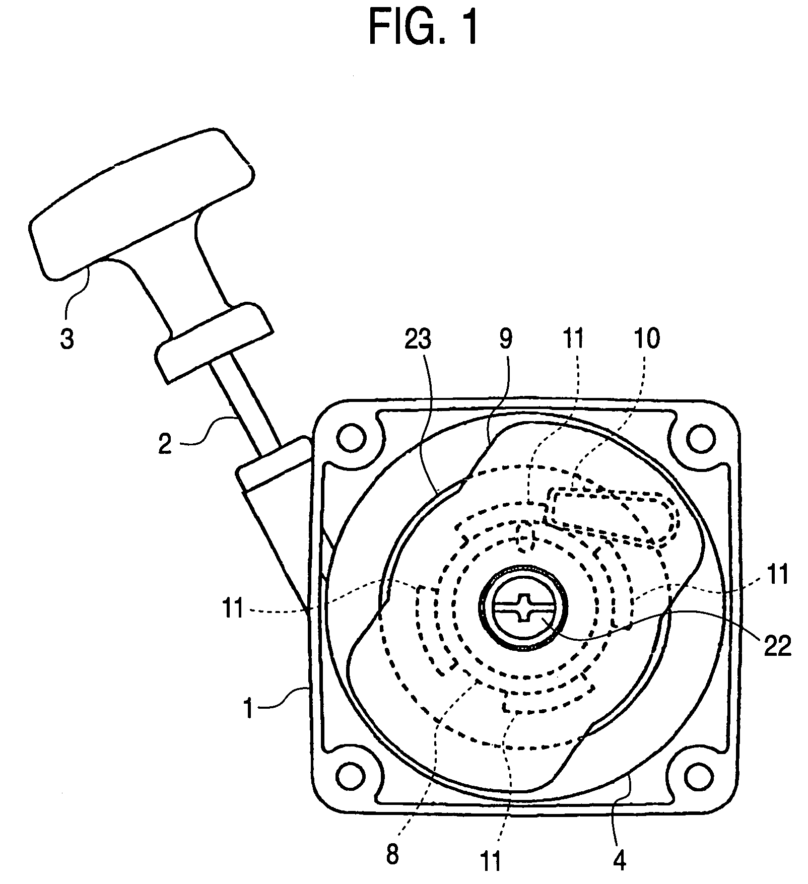
[0020]Hereinafter, an embodiment of the invention will be described based on an example shown in the drawings. In the recoil starter of the invention, as shown in FIG. 1, a handle 3 is coupled to an end portion of a recoil rope 2 which is exposed to the outside of a case 1. When the handle is pulled, a rope reel 4 housed in the case 1 is rotated, so that a rotary member 9 coupled to a crankshaft of an engine is rotated via a ratchet member 10 which is to be engaged with cam pawls 11 formed on an outer peripheral face of a cam 8 that is rotated by the rope reel 4. As a result, the engine is started.

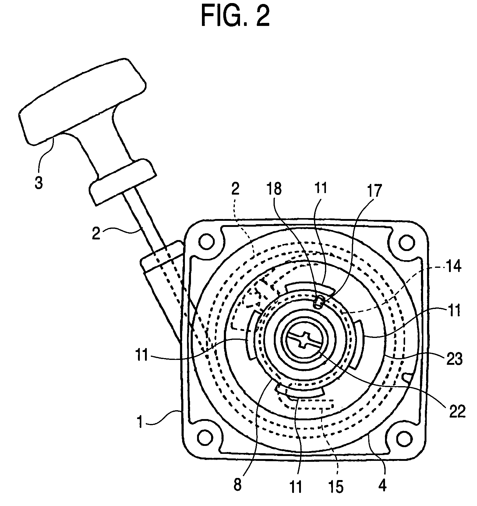
[0021]As shown in FIGS. 2 and 3, the rope reel 4 around which the recoil rope 2 is wound is rotatably supported by a support shaft 5 that is protruded inside the case 1 so as to be integral with the case 1. One end of the recoil rope 2 wound around the rope reel 4 is led to the outside of the case 1, and the other end of the rope is fixed to the rope reel 4. The tip of the one end which is...


PUM


Abstract

A damper spring having a torsion coil spring-like shape is placed on outer peripheries of bosses respectively formed on a rope reel and a cam. The ends of the damper spring are engaged with the rope reel and the cam, respectively, so that the rope reel and the cam are rotatingly coupled with each other. A wire member constituting the damper spring is formed so as to have a section shape in which at least one side is linearly formed, and the damper spring is formed by winding the wire member into a coil-like shape so that the linear portion of the wire member is placed on an inner peripheral side, thereby enabling the inner side face of the damper spring to be tightly wound in a wide area around outer peripheral faces of the bosses.

Description

BACKGROUND OF THE INVENTION[0001]1. Field of the Invention[0002]The present invention relates to a recoil starter in which a rope reel is rotated by pulling a recoil rope wound around the rope reel, the rotation of the rope reel is transmitted via a one-way clutch mechanism such as a centrifugal ratchet mechanism to a rotary member such as a flywheel magnet coupled to a crankshaft of an engine, to rotate the rotary member, whereby the crankshaft is rotated to start the engine.[0003]2. Description of the Related Art[0004]It has been known to employ the following structure in a recoil starter in which a rope reel is rotated by pulling a recoil rope wound around the rope reel, and the rotation of the rope reel is transmitted via a one-way clutch mechanism such as a centrifugal ratchet mechanism to a rotary member such as a flywheel magnet or a driving pulley coupled to a crankshaft of an engine, to rotate the rotary member, whereby the crankshaft is rotated to start the engine. A cam i...

Claims


Application Information

Patent Timeline
Patent Type & Authority Patents(United States)
IPC IPC(8): F02N3/02F16F1/06
CPCF16F1/06F02N3/02F02N5/02
Inventor TOHYAMA, ISAO
Owner STARTING IND CO LTD
Learn More