
Container retainer

a container and retainer technology, applied in the field of container mounting, can solve the problems of time-consuming and/or difficult to turn the screw to a sufficient tightness, affecting the use of containers, and preventing the use of certain container shapes and sizes, so as to reduce the handling of the dispenser, improve hygiene, and reduce the clutter around the sink area

Inactive Publication Date: 2012-05-10
HORNBEAM IVY
View PDF18 Cites 7 Cited by
  • Summary
  • Abstract
  • Description
  • Claims
  • Application Information

AI Technical Summary

Benefits of technology

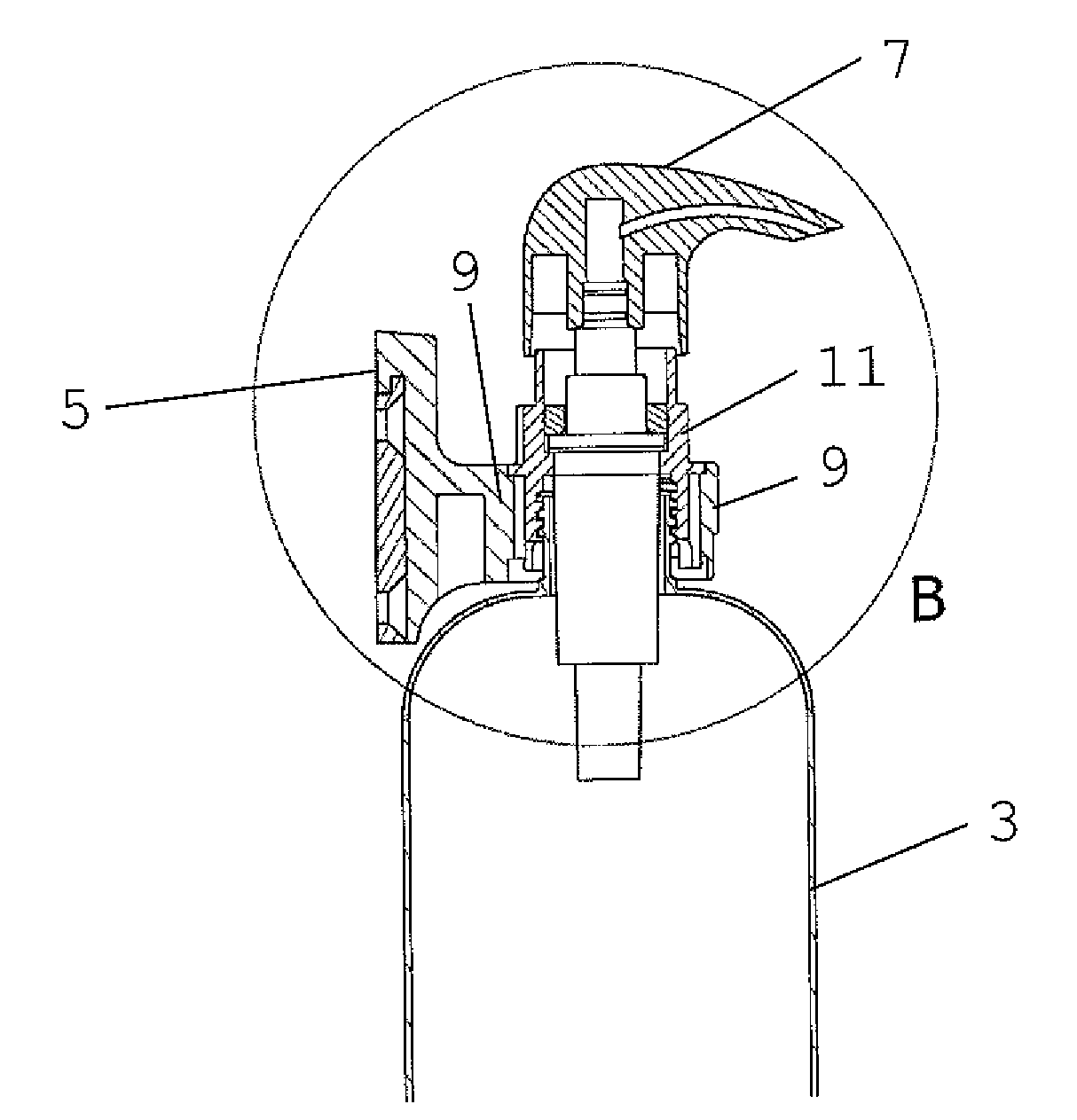
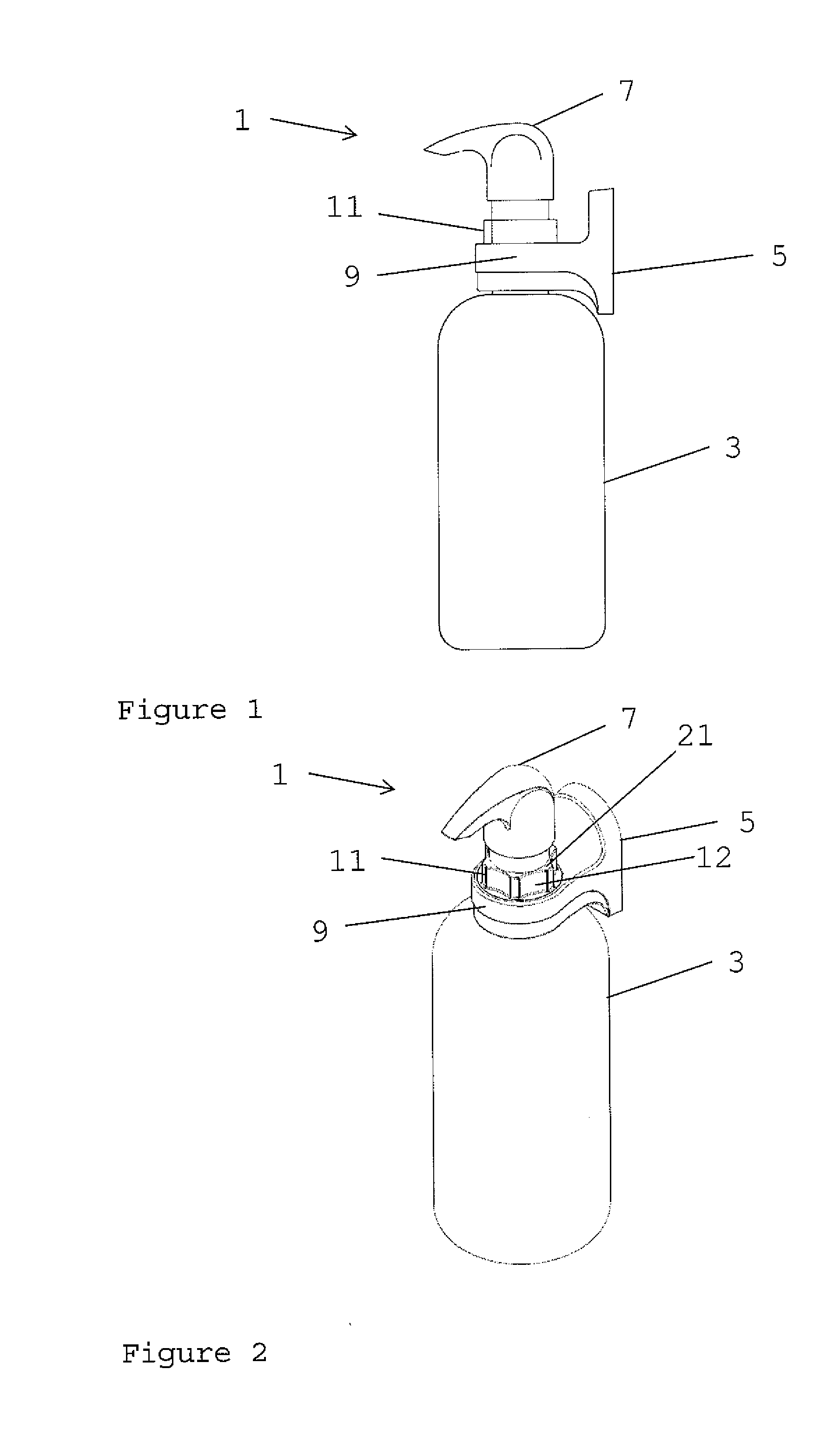
[0007]At its most general, the present invention provides a container retainer in which a locking member which can be mounted on the neck of a bottle is itself rotatably held in a body part, which body part is mountable on a suitable surface. With such an arrangement, it is possible to secure the locking member to the bottle by rotation without having to rotate the bottle itself, or the body part.
[0011]The locking member may be releasably held in the bore. This allows the container retainer to be assembled, and also to enable the locking member to be released e.g. for cleaning.
[0014]There may also be a flange on the locking member, which abuts against the body part adjacent one end of the bore, to resist axial movement of the locking member relative to the bore in one direction. The flange assists the lugs described above in retaining the locking member in the bore, but also has the effect of positioning the locking member at a predetermined axial position in the bore. This prevents the locking member moving axially, at least when it is not to be released. This effect may further be improved by providing a groove adjacent to the bore in which the flange is received, which then provides both axial and radial positioning of the locking member in the bore.
[0015]The locking member may have a grip part outside the bore to enable a user to rotate the locking member in the bore. The grip part may enable a user to more easily rotate the locking member to secure the locking member to the neck of a container. The grip part may also enable a user to apply a larger rotational force to the locking member relative to a locking member with no grip part, so that the locking member may be more tightly secured to the neck of the container.
[0020]A resilient member may be provided between the locking member and the bore to resist rotation of the locking member relative to the body part. Thus, to rotate the locking member relative to the body part, a user must apply a sufficient rotational force to overcome the resistance caused by the compression of the resilient member between the locking member and the bore.Undesired rotation of the locking member within the bore of the body part may thus be prevented.

Problems solved by technology

However, it can be time consuming and / or difficult to turn the screw to a sufficient tightness to prevent slip of the container.
However, these retaining mechanisms cannot be rotated when mounted to a surface, and thus it is necessary to rotate the container relative to such mechanisms to lock the container in place.
This can be difficult in cramped locations and preclude the use of certain container shapes and sizes.

Method used


Image

  • Container retainer
  • Container retainer
  • Container retainer

Examples


second embodiment

[0037]In the invention, as illustrated in FIG. 7, the locking member 11 is provided with first 23 and second 25 screw threads which are axially separated along the aperture 19 of the locking member 11, and which have different internal diameters (i.e. across the aperture 19 of the locking member 11). In this embodiment, first screw thread 23 with an internal diameter of 28 mm is provided on the locking member 11 towards the end of the bore 8 of the body part 9 that receives the neck of the container 3. Second screw thread 25 with an internal diameter of 24 mm is provided on the locking member 11 towards the other end of the bore 8.

[0038]Thus, when a neck of a container 3 having a screw thread with a diameter of 28 mm is inserted into the aperture 19 of the locking member 11, and the locking member 11 is rotated within the bore 8 relative to the body part 9, the first screw thread 23 engages with the screw thread on the neck of the container 3 to secure the locking member 11 to the n...

first embodiment

[0043]In other embodiments, the circlip 31 may be replaced with lugs 17, as described above in relation to the

[0044]The second embodiment has a conventional spring-loaded pump system 7, as known to a person skilled in the art and as described above in relation to the first embodiment. The pump system 7 gains access to the liquid contents of the container 3 through the aperture 19 of the locking member 11

[0045]A circumferential groove and O-ring as described above in relation to the second embodiment may similarly be included in the first embodiment of the invention. Similarly, a releasable circlip as described above in relation to the second embodiment may be included in the first embodiment in place of the lug arrangement.


PUM


Abstract

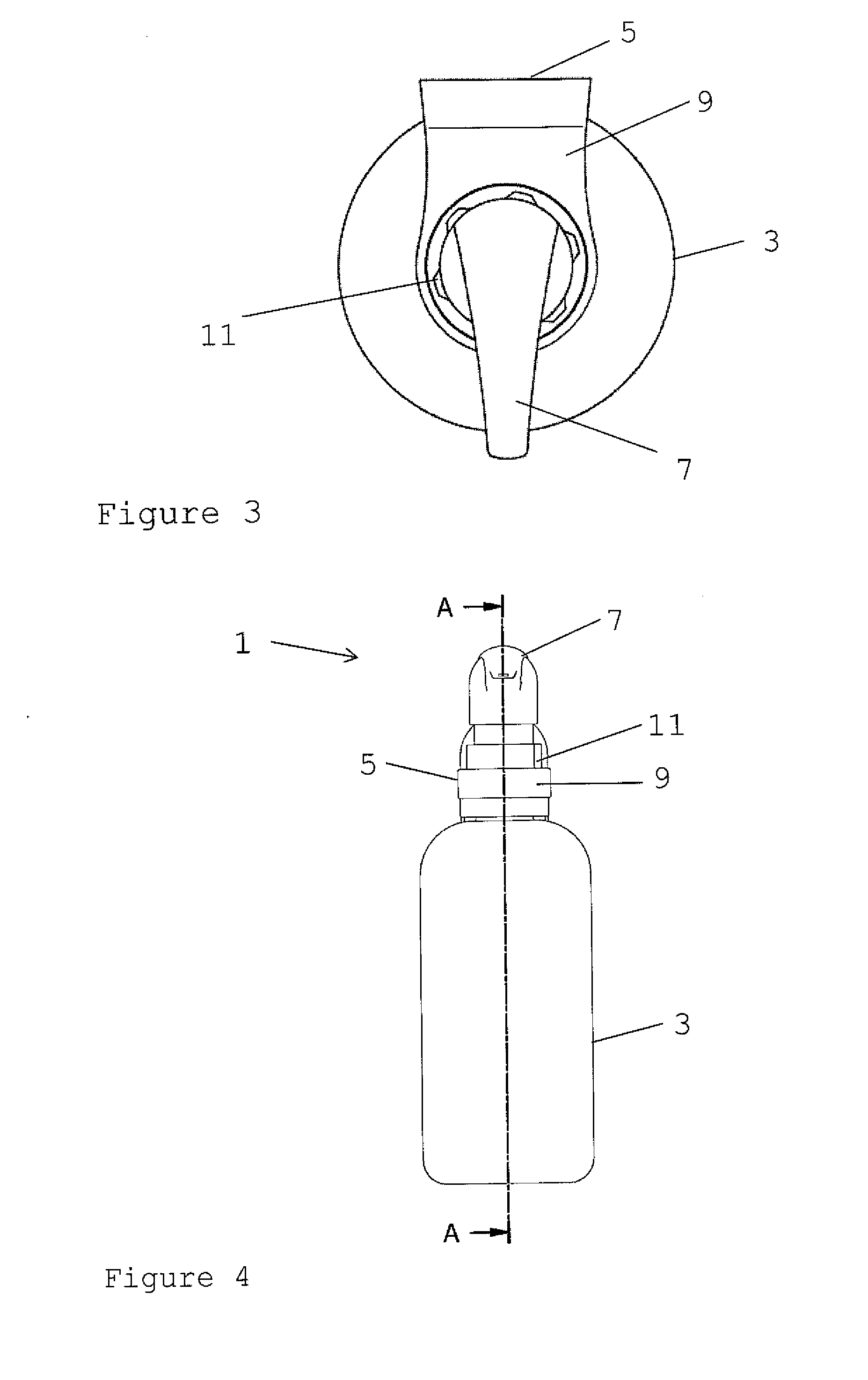
A container retainer (5) is provided in which a locking member (11) which can be mounted on the neck of a bottle (3) is itself rotatably held in a bore (8) of a body part (9). The body part (9) is mountable on a suitable surface, such as a wall. With such an arrangement, it is possible to secure the locking member (11) to the bottle (3) by rotation, without having to rotate the bottle (3) itself, or the body part (9). The container retainer (5) then will normally be wall mounted, to form a liquid dispenser to dispense liquid from the bottle (3) or other container (3).

Description

BACKGROUND OF THE INVENTION[0001]1. Field of the Invention[0002]The present invention relates to the mounting of containers on surfaces, such as walls. For example, the present invention may be used in a wall-mounted dispenser for dispensing liquids such as soap from a container.[0003]2. Summary of the Prior Art[0004]Pump dispensers for dispensing liquid products are known. Such pump dispensers typically have a dispenser pump with a variable-volume pump chamber mounted on a container of liquid product. Some pump dispensers are designed to be mounted on a wall, for example above a sink in a public convenience or a hospital. Mounting the pump dispenser on a wall has the advantages of reducing clutter around the sink area and of improving hygiene, for example by reducing handling of the dispenser and by preventing it from being knocked into the sink or onto the floor.[0005]With a wall-mounted pump dispenser, the pumping mechanism is typically a fixed feature, while the container of liq...

Claims


Application Information

Patent Timeline
IPC IPC(8): B67D7/06A47G29/08
CPCA47K5/12A47K2201/02
Inventor HERRING, WILLIAM PETERMOORE, JAMES
Owner HORNBEAM IVY
Learn More