Electric stapler and operation method of electric stapler

a technology of electric stapler and operation method, which is applied in the direction of nail dispensers, paper/cardboard containers, manufacturing tools, etc., can solve the problems of reduced penetration performance, increased price of electric stapler, and reduced binding performance of electric stapler, so as to reduce operation noise

Active Publication Date: 2013-02-12
MAX CO LTD
View PDF18 Cites 797 Cited by
  • Summary
  • Abstract
  • Description
  • Claims
  • Application Information

AI Technical Summary

Benefits of technology

[0015]One or more embodiments of the invention provide an electric stapler and an operation method of the electric stapler which are capable of reducing operation noise during binding processing without causing upsizing of an external form of a product or an increase of a number of parts.
[0018]In the electric stapler and the operation method of the electric stapler according to the embodiments, the motor control unit reduces the driving speed of the motor in the steps excluding the penetration step and the clinch step, so that driving noise of the motor in binding processing, operating noise of various operating members constructing the electric stapler, impulsive noise occurring in the case where various operating members abut mutually impulsively, etc. can be reduced.
[0019]On the other hand, in the penetration step and the clinch step, necessary output torque is maintained by not reducing the driving speed of the motor, so that sufficient driving force of the motor can be ensured in the penetration step in which a high penetration load is required in order to penetrate the legs of the staple into the paper bundle and also, the sufficient driving force of the motor can be ensured in the clinch step in which a high folding load is required in order to fold the legs of the staple. As a result of this, even when the driving speed of the motor is reduced and the driving noise etc. are reduced, the necessary driving force of the motor can be ensured in the penetration step and the clinch step, so that a reduction in binding performance of the electric stapler can be prevented.
[0020]Moreover, in the electric stapler and the operation method of the electric stapler according to the embodiments, the driving speed of the motor can be controlled by the motor control unit, so that driving speed control of the motor can be performed at various timings and driving speeds without changing components for example, an upward and downward movement mechanism of the table part, a structure of the driver unit or a structure of the clinch device for implementing the paper bundle pinching step, the staple separation step, the penetration step, the clinch step and the paper bundle releasing step. As a result of this, there is no need to use a special component such as a high-performance motor, a gear box or a belt conversion mechanism and also, an increase in management cost or component cost or an increase in a kind of product associated with an increase in the number of components can be reduced.
[0022]In the above structure in which a main driving gear driven by the motor and a rotational state detection device for detecting a rotational state of the main driving gear may be disposed, the motor control unit may determine processing timing of processing steps including the penetration step and the clinch step based on the rotational state of the main driving gear detected by the rotational state detection device and may reduce the driving speed of the motor.
[0023]According to the above structure in which the motor control unit may determine the processing timing of the processing steps including the penetration step and the clinch step by detecting the rotational state of the main driving gear by the rotational state detection device, since each of the processing steps of the binding processing may be executed based on the rotational state of the main driving gear rotated with the rotary driving of the motor, so that the processing timing of various processing steps can easily be determined by obtaining the rotational state of the main driving gear.

Problems solved by technology

However, for example, if the electric stapler designed to be driven by a voltage of 24 V is driven by a voltage of 12 V so that the driving speed of the motor is uniformly decreased, a reduction in penetration performance at the time of penetrating the staple into the paper bundle, a reduction in clinch force necessary for processing for clinching the legs of the staple, etc. occur so that there was a problem that binding performance (the bindable number of sheets, etc.) in the electric stapler may be reduced.
However, when the high-performance motor is used, a price of the electric stapler rises and also the number of products increases as a kind of motor increases and there was a problem that management cost or component cost may increase.
Also, a method for disposing a gear box or a belt variable speed mechanism is contemplated, but there was fear that the price rises and the number of products increases similarly.
Further, a method for preventing the noise from being propagated to an outside by accommodating the whole electric stapler in a soundproof box etc. is contemplated, but there was a problem of causing upsizing of an external form of a product.

Method used


Image

  • Electric stapler and operation method of electric stapler
  • Electric stapler and operation method of electric stapler
  • Electric stapler and operation method of electric stapler

Examples


Embodiment Construction

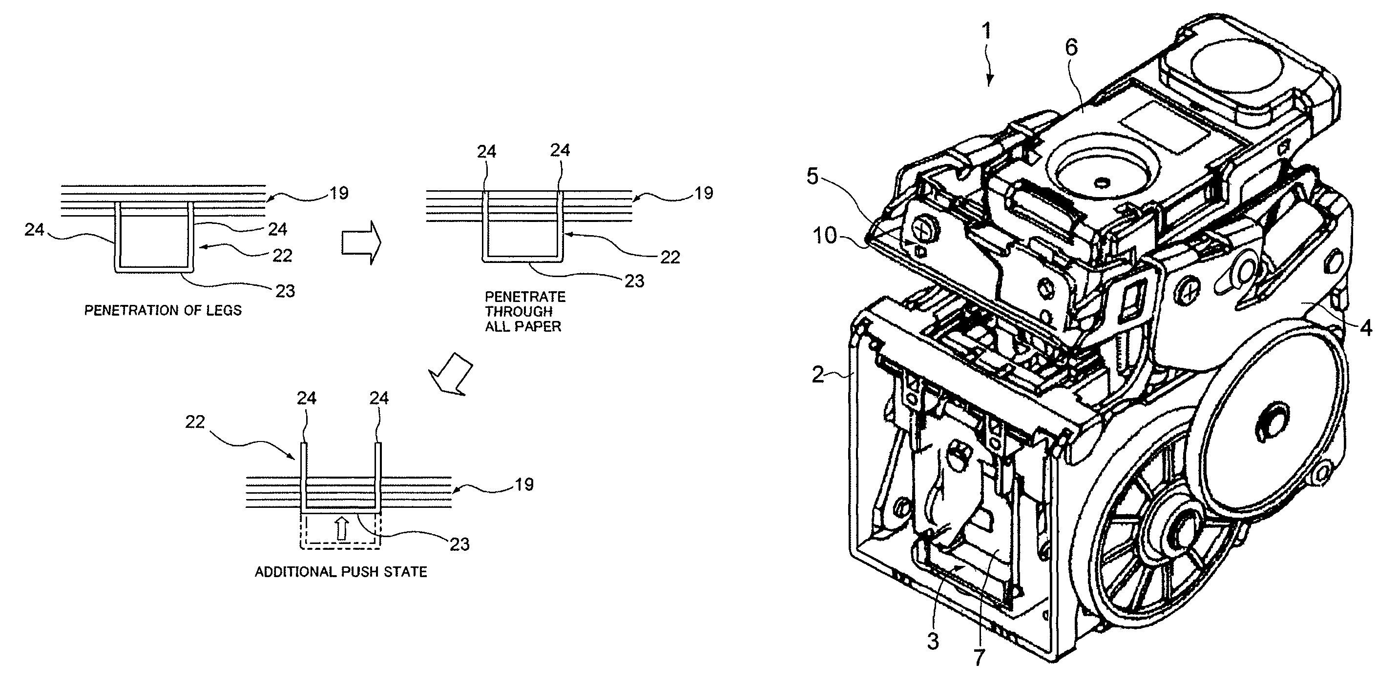
[0032]An electric stapler according to an exemplary embodiment of the invention will hereinafter be described with reference to the drawings. In addition, the electric stapler according to the exemplary embodiment includes a configuration similar to that of the general electric stapler 1 described already. Therefore, the same numerals are assigned to the portions made of the same configuration as the configuration described already and also its detailed description is omitted in the exemplary embodiment.

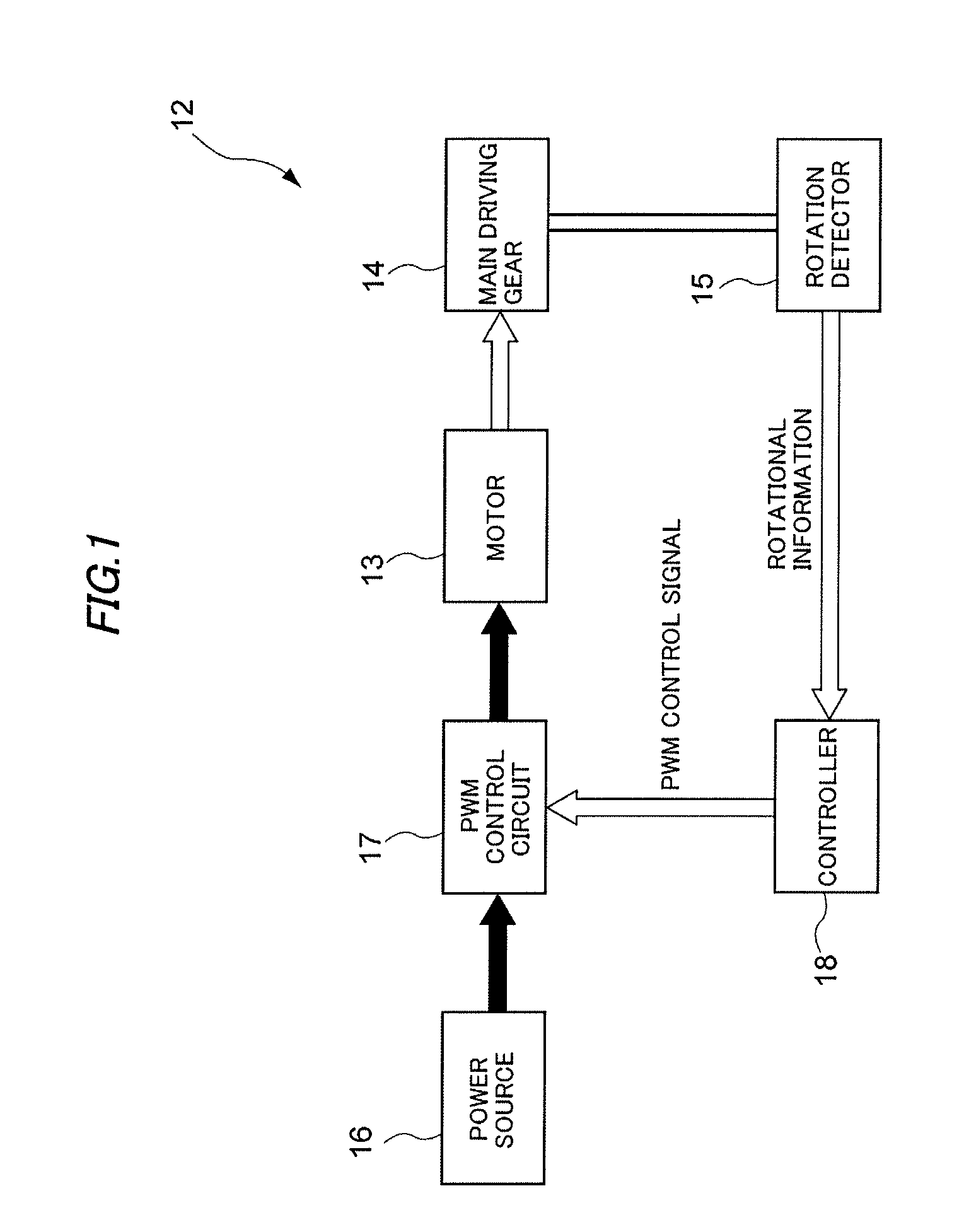
[0033]FIG. 1 is a block diagram showing a schematic configuration of a functional part for performing driving control of a motor in the electric stapler according to the exemplary embodiment.

[0034]An electric stapler 12 has a motor 13, a main driving gear 14 rotated and driven by the motor 13, a rotation detector (a rotational state detection device) 15 for detecting a rotational state of the main driving gear 14, a PWM (Pulse Width Modulation) control circuit (motor control unit) 17...


PUM


Abstract

An electric stapler is operated by a paper bundle pinching step of relatively moving a table part and a driver unit and also pinching a paper bundle; a staple separation step of folding a staple into U-shape by a forming plate and also separating the folded U-shape staple from a staple sheet by moving a driver; a penetration step of penetrating legs of the staple into the paper bundle by further moving the driver; a clinch step of inward folding the legs by a clinch device; and a paper bundle releasing step. A relative movement of the table part and the driver unit, the forming plate, the driver, and the clinch device are powered by a single motor. A driving speed of the motor in the steps excluding the penetration step and the clinch step is slower than the driving speed of the motor in the penetration step and the clinch step.

Description

BACKGROUND OF THE INVENTION[0001]1. Field of the Invention[0002]The present invention relates to an electric stapler and an operation method of the electric stapler, and more particularly to an electric stapler for performing binding processing by implementing a paper bundle pinching step, a staple separation step, a penetration step, a clinch step and a paper bundle releasing step, and a motor driving method in the electric stapler.[0003]2. Background Art[0004]An electric stapler for penetrating a staple into a bundle of a plurality sheets of paper (hereinafter called a “paper bundle”) and binding the paper bundle by electric power is known conventionally (for example, see Patent Reference 1, Patent Reference 2 and Patent Reference 3).[0005][Patent Reference 1] JP-A-2001-191265[0006][Patent Reference 2] JP-A-8-187681[0007][Patent Reference 3] JP-A-2006-116638[0008]FIG. 7 is a perspective view showing one example of the electric stapler. A driver unit 3 for forming and driving a sta...

Claims


Application Information

Patent Timeline
Patent Type & Authority Patents(United States)
IPC IPC(8): B25C7/00B25B21/02
CPCB27F7/36B27F7/19
Inventor HIGUCHI, KAZUOSHIMAMURA, MASASHI
Owner MAX CO LTD
Why Eureka
Try Eureka