Supercharge Your Innovation With Domain-Expert AI Agents!

Clamping device and coating apparatus having same

a technology of clamping device and coating apparatus, which is applied in the field of coating technology, can solve the problems of substratum distorted, inability to meet the requirements of use,

Inactive Publication Date: 2013-02-12
HON HAI PRECISION IND CO LTD
View PDF14 Cites 4 Cited by
  • Summary
  • Abstract
  • Description
  • Claims
  • Application Information

AI Technical Summary

Benefits of technology

Ensures uniform coating of IR cut-off films by maintaining the substrate's flatness and preventing distortion, thereby enhancing the optical performance of the infrared cut-off filters.

Problems solved by technology

However, the evaporation process is generally applied with a high temperature above about 200° C., and the substrate tends to get distorted in such a high temperature.
In such case, the IR cut-off film may not be coated on the substrate uniformly, and thus optical performance of the Infrared cut-off filter may be diminished in certain applications.

Method used


Image

  • Clamping device and coating apparatus having same
  • Clamping device and coating apparatus having same
  • Clamping device and coating apparatus having same

Examples


Embodiment Construction

[0012]Embodiment of the coating apparatus will now be described in detail below and with reference to the drawings.

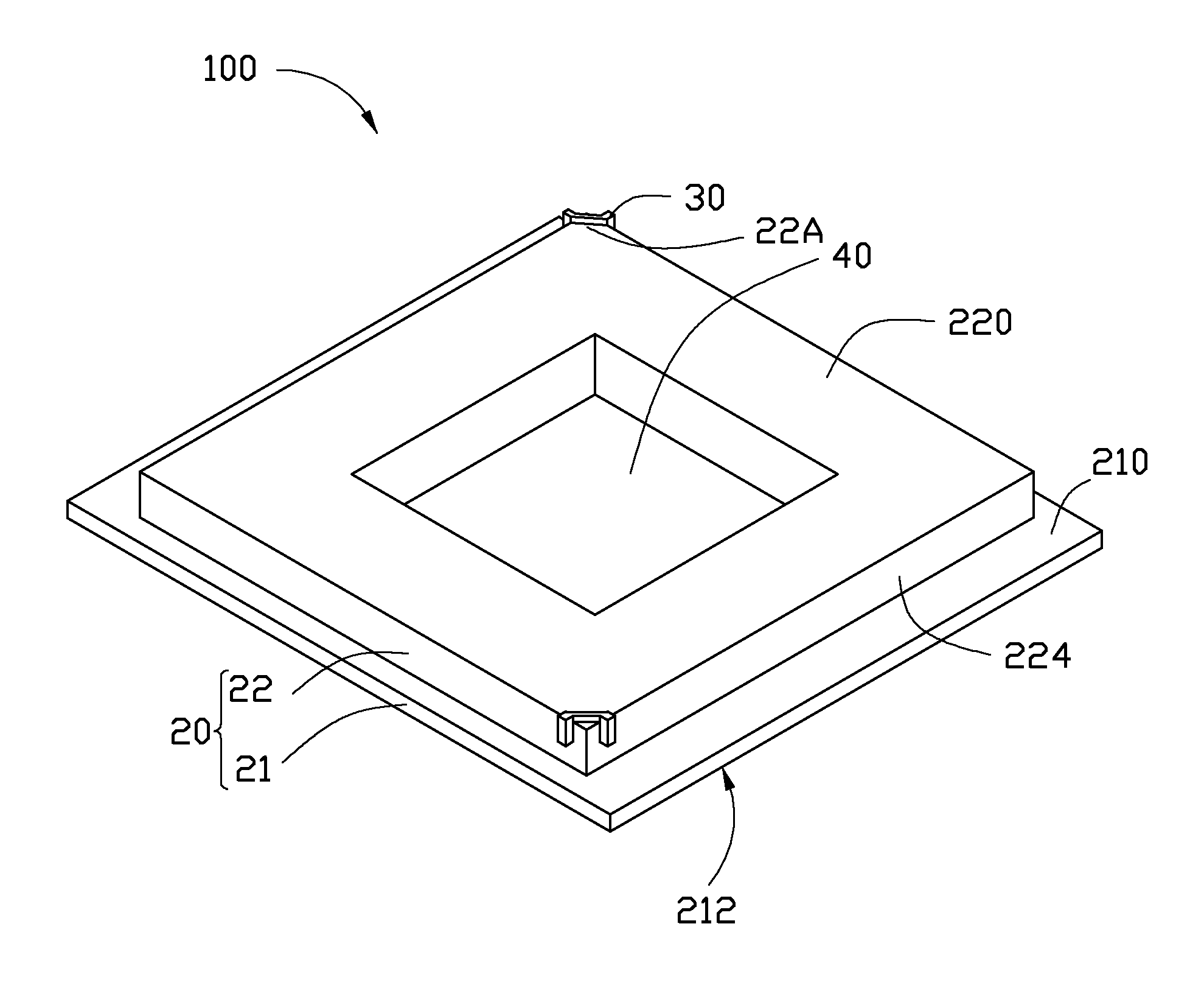
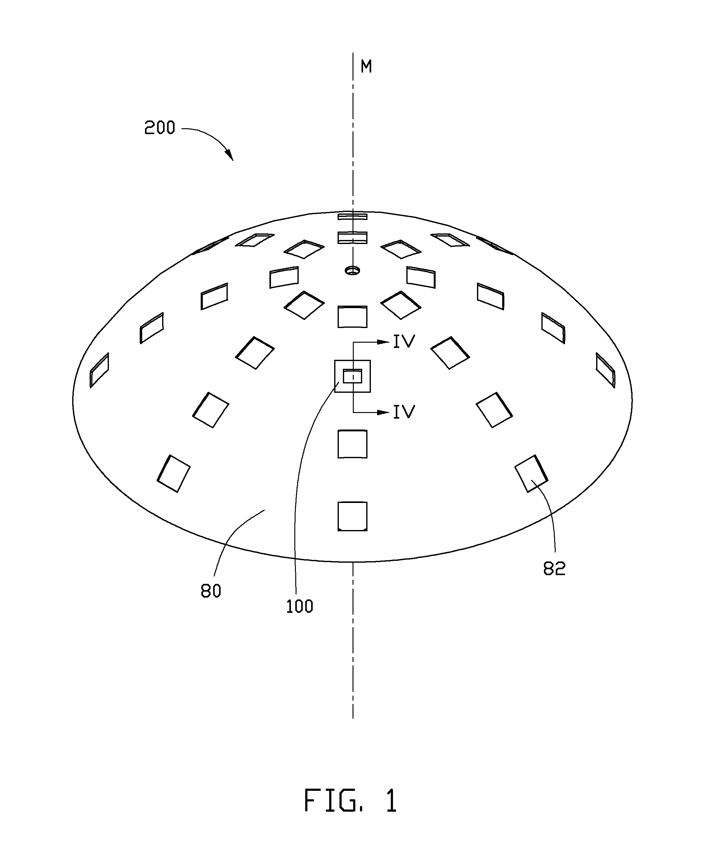
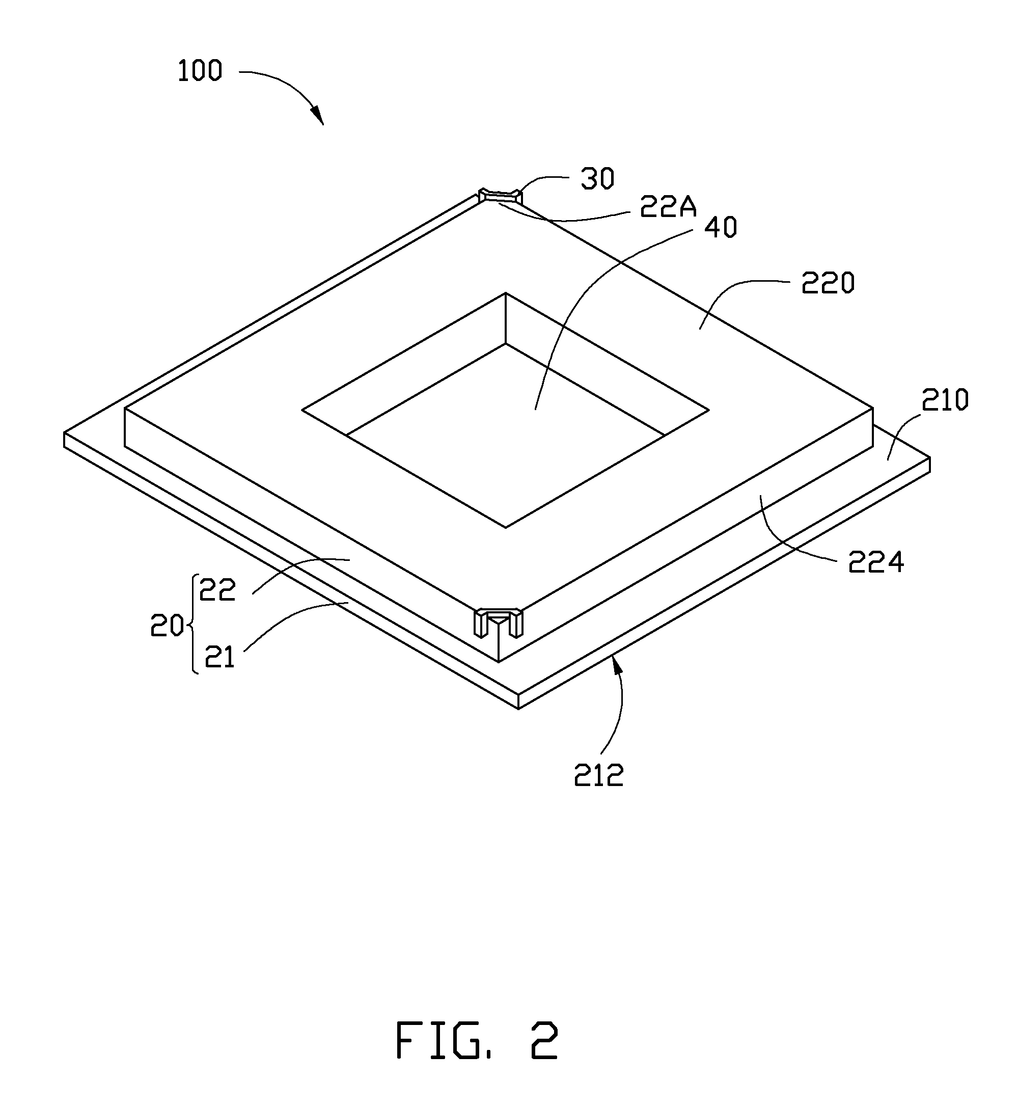
[0013]Referring to FIG. 1, a coating apparatus 200 in accordance with an exemplary embodiment is shown. The coating apparatus 200 includes a support frame 80 and a number of clamping devices 100.

[0014]Referring also to FIG. 2 to FIG. 4, the support frame 80 includes a support surface 810, and a concave surface 812 facing away from the support surface 810 (see FIG. 4). In this embodiment, the support frame 80 is a curved plate, and includes a central axis M. The support frame 80 has a number of receiving holes 82 defined in the support surface 810. In this embodiment, the receiving holes 82 surround the central axis M, and are evenly dispersed on the support surface. The receiving hole 82 is generally cuboid-shaped. In alternative embodiments, the support frame 80 may have another shape, for example, a cuboid-shape. The support surface 810 and the concave surface 812 eac...


PUM

PropertyMeasurementUnit
temperatureaaaaaaaaaa
surface areaaaaaaaaaaa
mid-infrared wavelengthsaaaaaaaaaa

Abstract

A clamping device for clamping a substrate with a first surface and a second surface includes a supporting plate and a number of clamping units. The supporting plate includes a base portion and an engaging portion. The base portion includes a base surface. The engaging portion protrudes from the base surface of the base portion and includes an engaging surface facing away from the base surface. The supporting plate defines a through hole in the engaging surface. The supporting plate is configured for supporting the substrate on the engaging surface of the engaging portion. The clamping units are configured for clamping the substrate on the supporting plate such that the engaging surface of the engaging portion engaging surface is substantially coplanar with the first surface of the substrate.

Description

BACKGROUND[0001]1. Technical Field[0002]The disclosure relates to coating technology and, particularly, to a coating apparatus with a clamping device.[0003]2. Description of Related Art[0004]Infrared (IR) cut-off filters are configured to reflect or block mid-infrared wavelengths while passing visible light, and are generally equipped in cameras as key elements thereof. The IR cut-off filters are manufactured by forming IR cut-off films on substrates by applying an evaporation process, or another coating method such as sputtering process.[0005]Generally, when coating an IR cut-off film on a surface of the substrate using for example, an evaporation process, a clamping device may first be provided to clamp the substrates. And then a functional material can be evaporated on the surface of the substrates to form the optical film. A typical clamping device generally includes two clamping jaws. In use, the two clamping jaws abut against two peripheral sides of the substrate. However, the...

Claims


Application Information

Patent Timeline
Patent Type & Authority Patents(United States)
IPC IPC(8): B25B1/00
CPCB25B5/06B25B5/142H01L21/68771C23C14/50H01L21/68728B25B11/00
Inventor TSAI, TAI-SHENG
Owner HON HAI PRECISION IND CO LTD
Features
  • R&D
  • Intellectual Property
  • Life Sciences
  • Materials
  • Tech Scout
  • Unparalleled Data Quality
  • Higher Quality Content
  • 60% Fewer Hallucinations
Learn More