
Medical implant

a technology of medical implants and implants, applied in the field of medical implants, can solve the problems that the proportion of such occlusion means cannot be prevented from exiting, and achieve the effect of preventing the proportion of such occlusion means from exiting

Active Publication Date: 2013-02-12
TYCO HEALTHCARE GRP LP
View PDF126 Cites 26 Cited by
  • Summary
  • Abstract
  • Description
  • Claims
  • Application Information

AI Technical Summary

Benefits of technology

This patent describes a method for stabilizing an aneurysm wall to prevent rupture and facilitate the insertion of filamentous occlusion means without risking rupture. However, there is a risk of rupture in areas adjacent to faces and edges of the aneurysm, as well as the helixes subsequently inserted. The use of a pentagonal dodecahedron helix arranged on a vertex or corner point was found to be particularly beneficial in preventing the helix from slipping out of the neck and being flushed out. The distal end of the helix is located in a face and is a mainly atraumatic supporting location on a side facing away from the neck of the aneurysm. The technical effect of this patent is to provide a safer method for stabilizing an aneurysm wall and preventing rupture.

Problems solved by technology

Moreover, because of the largely openly configured tertiary structure of such occlusion means the subsequently inserted occlusion means or portions of such occlusion means can only be prevented from exiting through the neck of the aneurysm primarily in the case of small-neck aneurysms.

Method used


Image

  • Medical implant
  • Medical implant
  • Medical implant

Examples


Embodiment Construction

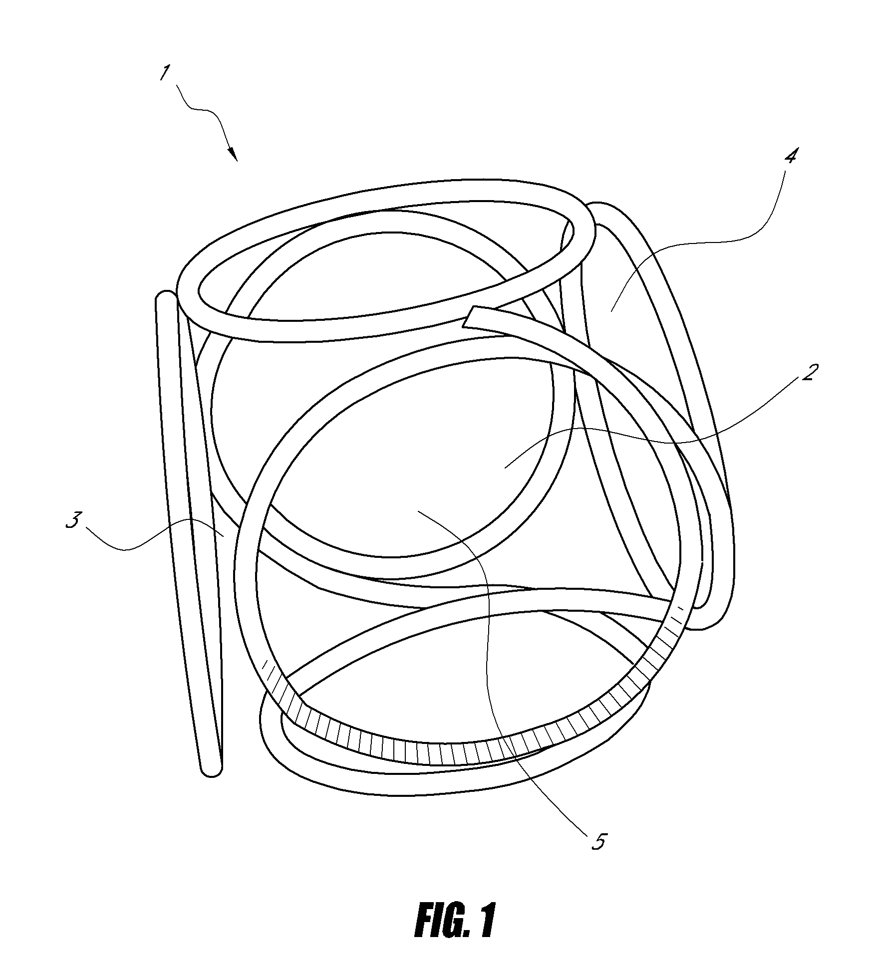
[0070]FIG. 1 represents a cube-shaped implant 1 of enlarged size reflecting the state of the art. The open configuration, especially of the faces 2 and vertex areas 4, but also of edges 3, is to be seen as a weak point of such implants 1 because the aneurysm wall in contact with them is particularly prone to rupture. In addition, the insufficient packing density of the implant 1 in the vicinity of said areas 2, 3 and 4 only prevents to a minor extent implants subsequently placed for the purpose of filling the inner hollow space 5 from being expelled again.

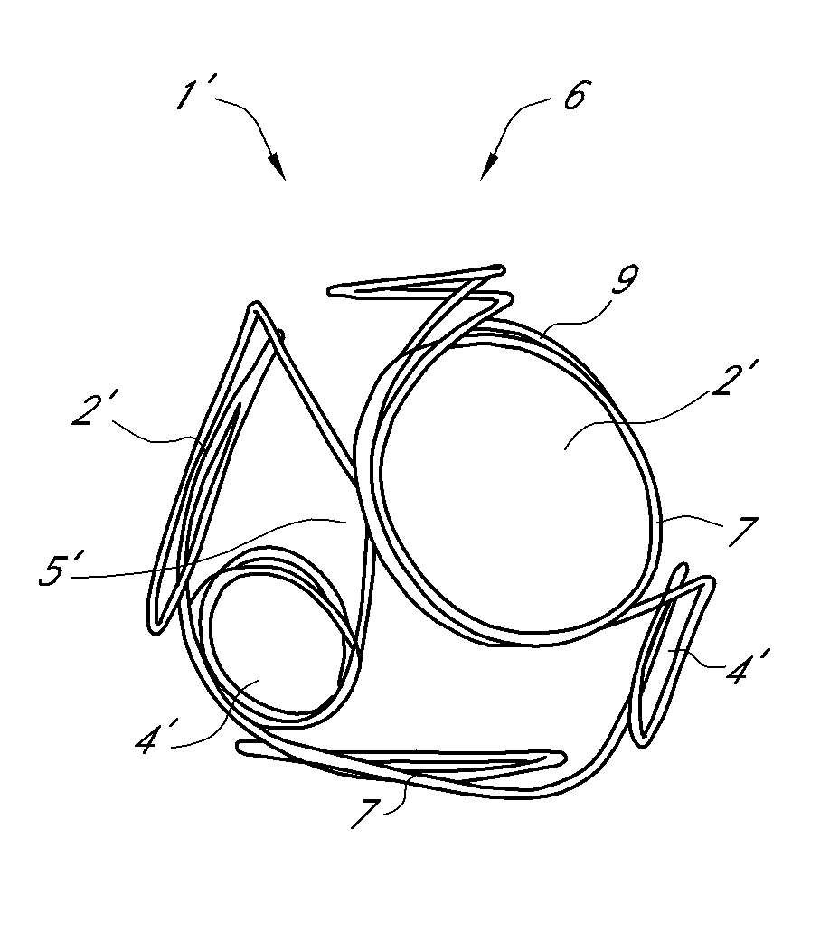
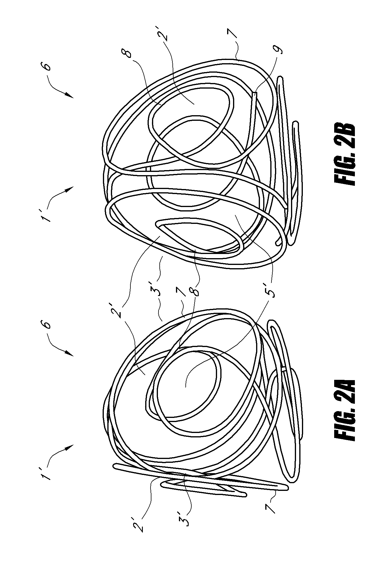
[0071]FIG. 2 shows two views 2a and 2b of a tetrahedron-shaped implant 1′ according to the invention, said implant having assumed its three-dimensional tetrahedral tertiary structure. The faces 2′ of tetrahedron 6 are built up by two uniformly sized large loops 7, two of which in each case being adjacently positioned, with the projections of the large loops 7 extending into the space constituted by the sectional areas of two neighb...


PUM

PropertyMeasurementUnit
diameteraaaaaaaaaa
diameteraaaaaaaaaa
diameteraaaaaaaaaa

Abstract

The invention relates to a medical implant in the form of an elongated helix wherein at least one part of the helix is preformed in such a manner that it has a secondary structure of identically sized loops which it assumes during implantation at the placement site, with said structure in turn forming at the placement site during implantation a polyhedral tertiary structure, and the polyhedron being provided with at least one additional loop.

Description

CROSS-REFERENCE TO RELATED APPLICATIONS[0001]This application is a continuation of U.S. application Ser. No. 11 / 575,798, filed May 1, 2008, which is incorporated in its entirety by reference, herein, and which is a national phase application of International Application No. PCT / EP2004 / 010610, filed on Sep. 22, 2004 and published in German on Mar. 30, 2006 as WO 2006 / 032289 A1, which is incorporated in its entirety by reference, herein.BACKGROUND[0002]1. Field of the Invention[0003]The invention relates to a medical implant in the form of an elongated helix wherein at least one part of the helix is preformed in such a manner that it has a secondary structure which it assumes during implantation at the placement site, with said structure in turn forming at the placement site during implantation a polyhedral tertiary structure, with each face of the polyhedron being built up by a loop.[0004]The invention, furthermore, relates to a device for the implantation of such implants in body ca...

Claims


Application Information

Patent Timeline
Patent Type & Authority Patents(United States)
IPC IPC(8): A61M29/00
CPCA61B17/12022A61B17/12113A61B17/12145Y10T29/49826A61B2017/00526A61B2017/00867
Inventor MONSTADT, HERMANNHENKES, HANSFLESSER, ACHIMHANNES, RALF
Owner TYCO HEALTHCARE GRP LP
Learn More