Energy absorbing structure for aircraft

a technology of energy absorption and aircraft, applied in the direction of aircraft accessories, fuselages, military adjustments, etc., can solve the problems of aircraft structural integrity loss, composite materials that are difficult to design, crash injuries, etc., to promote elastic stability during crushing, reduce the compression strength of the member, and reinforce the structural member

Active Publication Date: 2013-02-19
THE BOEING CO +1
View PDF15 Cites 18 Cited by
  • Summary
  • Abstract
  • Description
  • Claims
  • Application Information

AI Technical Summary

Benefits of technology

[0007]In accordance with one aspect of the invention, an energy absorbing structural member comprises an elongated body having first and second opposite ends, and first and second opposite sides. The body contains laminated plies of a reinforced composite material wherein the plies have varying lengths forming steps along the length of the member such that the compression strength of the member is progressively less from the first end to the second end. At least one reinforced flange on the body is tapered from the first to the second end, and functions to both reinforce the structural member and promote elastic stability during crushing. The laminated plies are preferably formed from reinforced composite materials such as a carbon fiber reinforced epoxy. In one embodiment, the structural member includes first and second reinforcing flanges extending along the length of the body, and third and fourth flanges integrally formed with the first and second flanges, for attaching the structural member to the floor of an aircraft.
[0008]In accordance with another aspect of the invention, an aircraft is provided, comprising: a fuselage; a floor including floor beams within the fuselage; and, an energy absorbing structure between the floor and the fuselage for absorbing energy in the event the fuselage is impacted during a crash. The energy absorbing structure includes a plurality of energy absorbing stanchions extending between the floor beams and the fuselage. Each of the stanchions includes a first end adjacent the floor beam and a second end adjacent the fuselage, wherein the compression strength of each of the stanchions progressively decreases from the first end to the second end. The stanchions are axially oriented at multiple angles relative to the floor beams so as to absorb lateral loads caused by non-vertical impacts when the aircraft rolls slightly before ground impact. The stanchions contain laminated plies of reinforced composite material, wherein the plies have varying lengths forming reduced ply steps along the length of the stanchion. The aircraft further comprises cross beams extending transverse to the floor beams, and first and second fittings for attaching each of the stanchions to both a floor beam and a cross beam. The stanchions preferably include a pair of spaced apart tapered flanges, which contribute to the elastic stability of the stanchions during crushing.
[0010]The energy absorbing floor structure of the invention provides a high level of energy absorbing capability at minimal cost and reduced weight. The design of the energy absorbing structure promotes controlled failure so that maximum energy is absorbed. Crush initiation of the cargo floor stanchions begins at the lower attachment of the stanchions to the fuselage frame, and subsequent progressive crushing of the stanchions proceeds in a stable manner while the stanchions maintain attachment to the cargo floor beams. This progressive, stable crushing reduces the possibility of stanchion buckling, and aids in maintaining the structural integrity of the cargo floor attachment during a crash.

Problems solved by technology

Crash injuries may be caused by high acceleration loads experienced by the occupants, or the loss of structural integrity of the aircraft.
Energy absorbing systems that use composite materials present a design challenge because these materials are often brittle and do not exhibit either plasticity or high elongation prior to failure.
These design solutions may sometimes be difficult to incorporate into manufacturing processes without significant cost increases.
In addition, previous design solutions were limited to protecting occupants from impact forces acting vertically on the aircraft, rather than from off-vertical forces which can be imposed on the fuselage if the aircraft rolls slightly before ground impact.

Method used


Image

  • Energy absorbing structure for aircraft
  • Energy absorbing structure for aircraft
  • Energy absorbing structure for aircraft

Examples


Embodiment Construction

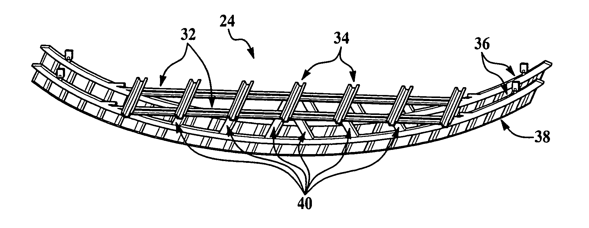
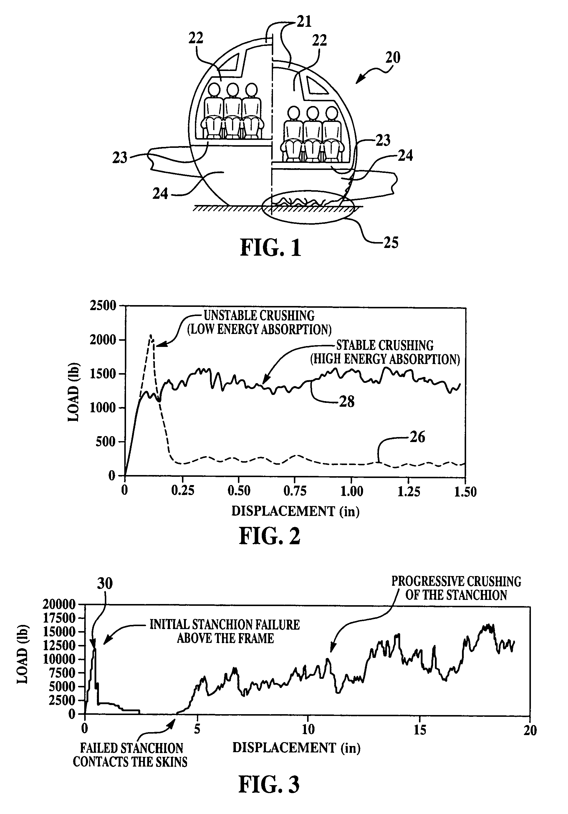
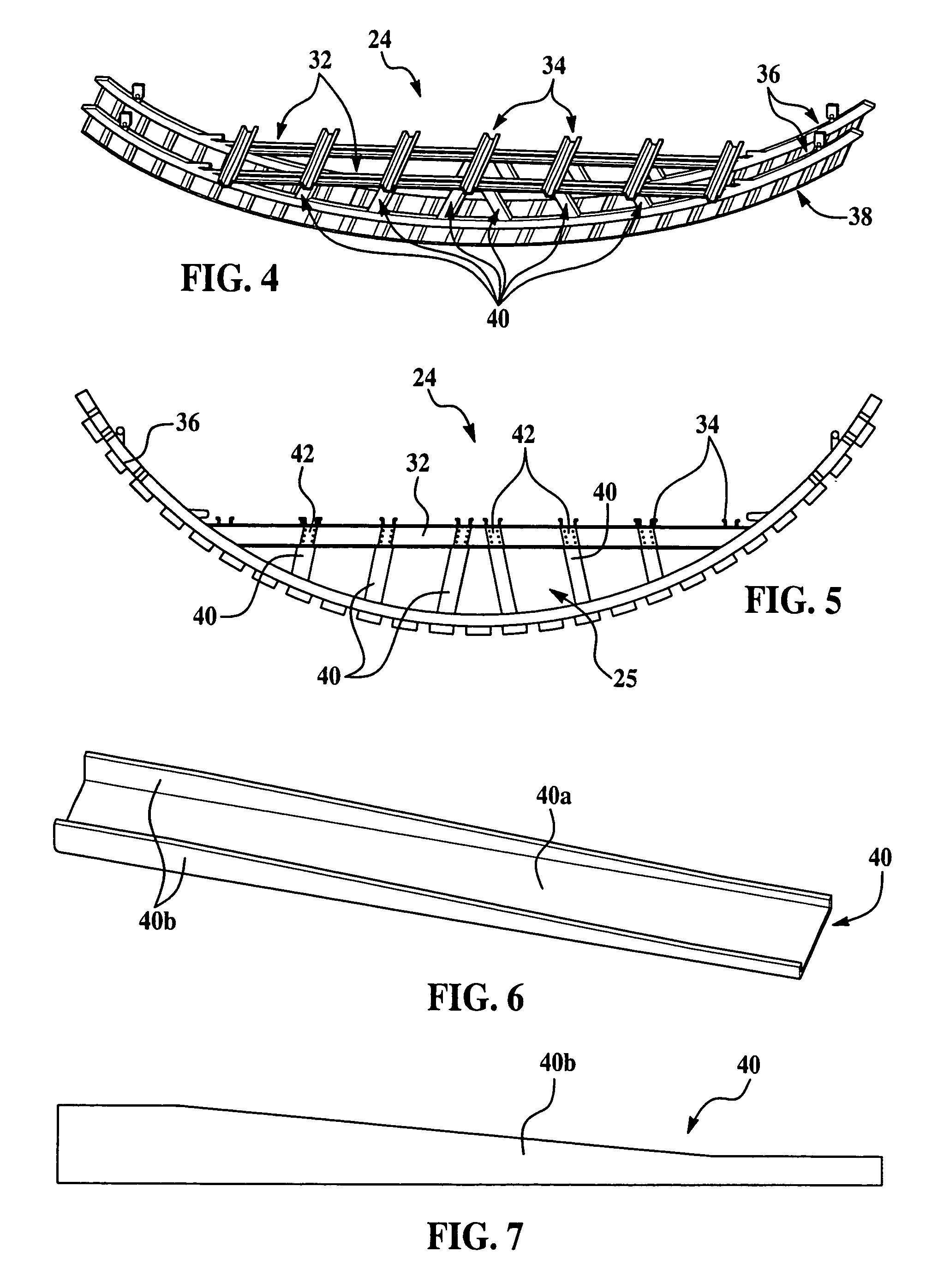
[0033]Referring first to FIG. 1, an aircraft generally indicated by the numeral 20 has a cylindrical fuselage 21 defining an interior space that is separated into upper and lower lobes by a floor 23. The upper lobe includes a passenger compartment 22 while the lower lobe contains a cargo area 24. A volume of space below the cargo area 24 is normally available to contain energy absorption structure and constitutes the part of the aircraft 20 that is first to impact the ground in the event of a wheels up landing. The left side of the aircraft 20 shown in FIG. 1 depicts the condition of the cargo area 24 before impact, while the right side of FIG. 1 shows the aircraft having impacted the ground during a crash, producing a crush area 25 where part of the fuselage 21 and internal support structure collapse. To improve crashworthiness, it is desirable that the structure within the crush area 25 crushes in a stable manner in order to provide the required energy absorption while maintaining...


PUM


Abstract

Energy absorbing structure disposed beneath the cargo area of an aircraft provides maximum energy absorption and structural strength using carbon fiber reinforced epoxy composites. The energy absorbing structure uses laminated stanchions having ply drop-offs to produce stable, progressive crushing of the stanchions during a wheels-up crash landing. Integrally formed flanges on the stanchions allow direct mounting of the stanchions on the structural members of the aircraft, without the need for specialized fittings.

Description

BACKGROUND OF THE INVENTION[0001]1. Field of the Invention[0002]This invention broadly relates to energy absorbing structures, and deals more particularly with energy absorbing elements such as stanchions and assembly fittings used in aircraft.[0003]2. Description of the Related Art[0004]An important objective in the design of modern military and civilian aircraft is the protection of occupants in the event of a survivable crash. Crash injuries may be caused by high acceleration loads experienced by the occupants, or the loss of structural integrity of the aircraft. Crashworthy designs for aircraft require the fuselage to provide energy absorption in order to slow down the aircraft during a crash impact. Controlled deceleration of the aircraft during impact reduces inertial loads on the occupants, and assists in maintaining structural integrity of the aircraft. The area beneath the fuselage floor can form an important part of the energy absorption system in the event of a crash, sin...

Claims


Application Information

Patent Timeline
Patent Type & Authority Patents(United States)
IPC IPC(8): B64C1/00
CPCB64C1/062B64C1/18
Inventor BOLUKBASI, AKIF O.BAXTER, THOMAS R.NGUYEN, TUAN A.RASSAIAN, MOSTAFADAVIS, KEVIN R.KOCH, WILLIAM J.FIRTH, LEE C.
Owner THE BOEING CO
Why Eureka
Try Eureka