Compressor protection device and compressor system

A compressor system and protection device technology, which is applied in the field of compressors, can solve problems such as larger vibration amplitude and tilt angle of the compressor, increased transportation costs, and compressor bumping into surrounding parts, etc., so as to reduce the vibration or tilt The effect of reducing the range of transportation costs and avoiding excessive deformation

Inactive Publication Date: 2017-12-12
GREE ELECTRIC APPLIANCES INC
View PDF5 Cites 1 Cited by
  • Summary
  • Abstract
  • Description
  • Claims
  • Application Information

AI Technical Summary

Problems solved by technology

[0004] However, the inventors of the present invention have found that the above-mentioned conventional compressor protection device has at least the following technical problems: Figure 1 to Figure 4 As shown, due to the limitation of the top step 222 of the bolt 22 and the material of the rubber pad 23 (softer rubber material), the height of the rubber pad 23 will decrease under the compression of the compressor 1, so the compressor nut There is a certain gap between the bottom of 25 and the top of the rubber pad 23; when the whole machine is violently shaken or subjecte

Method used


Image

  • Compressor protection device and compressor system
  • Compressor protection device and compressor system
  • Compressor protection device and compressor system

Examples


Embodiment 1

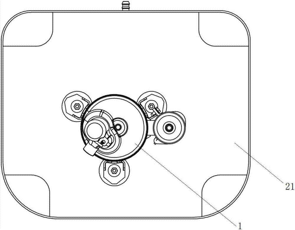
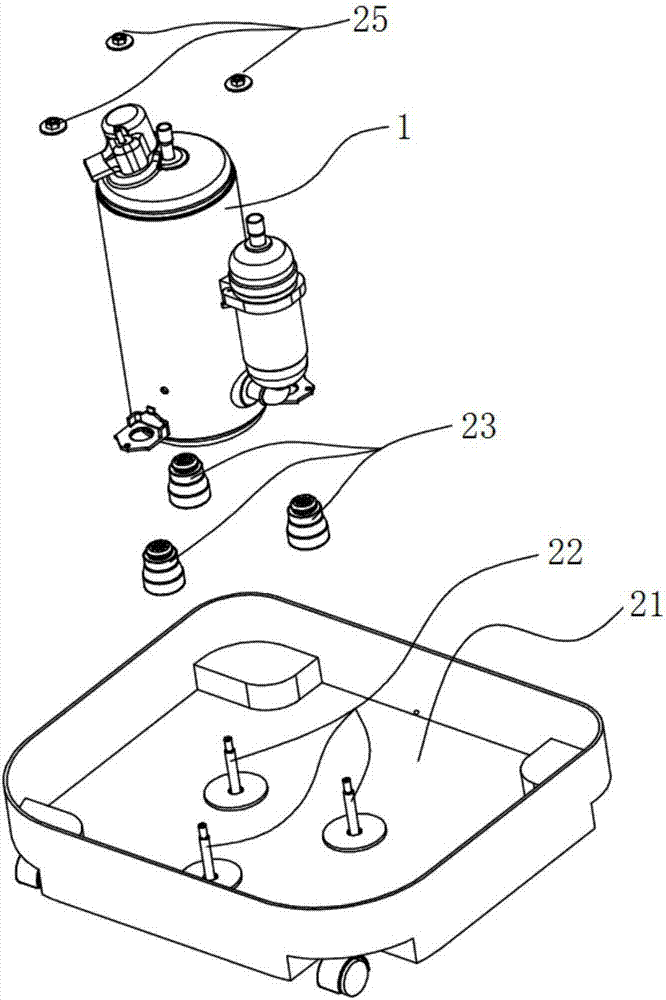
[0049] This embodiment provides a compressor protection device, such as Figure 5 to Figure 11 As shown, the protection device for the compressor in this embodiment includes a chassis 31 , a rubber pad 33 and a protection structure 34 . Wherein, the rubber pad 33 is limited on the chassis 31 by a limit structure (wherein, the specific design of the limit structure is detailed in the content described in Embodiment 4), and the rubber pad 33 is used to connect the fixing parts on the compressor 1 11. Wherein, the protective structure 34 is arranged on the chassis 31 and is used to limit the displacement of the fixing member 11 within a set range.

[0050]Because the rubber pad 33 is a relatively soft rubber material, when the compressor 1 shakes, under the action of the fixing member 11, the rubber pad 33 will be deformed (especially, the height of the rubber pad 33 will be reduced); When vibrating or receiving impacts such as falling, the rubber pad 33 will be excessively def...

Embodiment 2

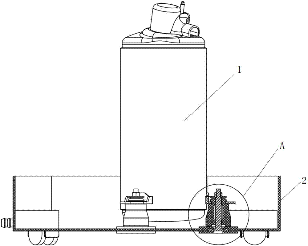
[0053] Preferably, this embodiment provides a compressor protection device, compared with the previous embodiment, such as Figure 10 and Figure 11 As shown, the protective structure 34 in the present embodiment can limit the displacement of the fixing member 11 to the direction of the chassis 31 (that is, as Figure 11 As shown, the displacement of the fixing member 11 moving downward).

[0054] The compressor protective device provided in this embodiment is provided with a protective structure 34 on the chassis 31 to limit the displacement of the fixing member 11 moving downward, thereby preventing the rubber pad 33 from being excessively compressed, so as to reduce the vibration or tilt of the compressor 1. range, and reduce the volume of electrical equipment, and reduce the transportation cost of electrical equipment.

Embodiment 3

[0056] Preferably, this embodiment provides a compressor protection device, compared with Embodiment 2, such as Figure 5 and Figure 6 , Figure 9 to Figure 11 As shown, the present embodiment further designs the protective structure 34 as follows:

[0057] When the fixing part 11 on the compressor 1 is connected to the rubber pad 33 , the protective structure 34 is located below the fixing part 11 , and the minimum distance d between the protective structure 34 and the fixing part 11 is a first set distance. Preferably, the first set distance is 0.2-5mm. Here, the protection device for the compressor provided in this embodiment directly locates the protection structure 34 under the fixing part 11 of the compressor 1 to limit the displacement of the fixing part 11 moving downward, thereby preventing the rubber pad 33 from being excessively compressed. Reduce the shaking or tilting of compressor 1.

[0058] Preferably, the protective structure 34 in this embodiment is arra...


PUM


Abstract

The invention provides a compressor protection device and a compressor system and relates to the technical field of compressors. The mainly adopted technical scheme is that the compressor protection device comprises a base plate, rubber pads and protection structures. The rubber pads are limited to the base plate through limiting structures, and the rubber pads are used for being connected with fixing pieces on a compressor; and the protection structures are arranged on the base plate and are used for limiting the displacement of the fixing pieces within the set range. The compressor protection device and the compressor system are mainly used for reducing the shaking or inclining amplitude of the compressor, so that the situation that the compressor collides and damages peripheral parts in the transport and work processes can be avoided; and the size of electrical equipment is further reduced, and the transport cost of the electric equipment is lowered.

Description

technical field [0001] The invention relates to the technical field of compressors, in particular to a compressor protection device and a compressor system. Background technique [0002] Electrical equipment with refrigeration and heating systems (such as air conditioners, dehumidifiers, refrigerators, etc.) are equipped with compressor components, but limited by the mechanism of the compressor, there is a high-speed driving motor inside, and there will be Vibration, therefore, the installation of the compressor cannot be completely locked and fixed. It is necessary to reserve a certain movable gap and free space for the compressor to avoid strong vibration and abnormal noise of other parts and the whole machine, shortening the life of the machine and affecting consumption. issues of experience. In addition, electrical equipment usually needs to be delivered from the factory to the market and then to consumers through long-distance transportation (such as land, sea, or air)...

Claims


Application Information

Patent Timeline
IPC IPC(8): F04B39/00
CPCF04B39/00F04B39/0044
Inventor 黄海强姚新详姚刚梁耀详李孟志罗炎赞林强练黄治华黄佛义
Owner GREE ELECTRIC APPLIANCES INC
Why Eureka
Try Eureka