LED lamp

a technology of led lamps and led tubes, applied in semiconductor devices for light sources, lighting and heating apparatus, lighting support devices, etc., can solve problems such as negative impact on people's eyes

Inactive Publication Date: 2013-02-19
HON HAI PRECISION IND CO LTD
View PDF7 Cites 47 Cited by
  • Summary
  • Abstract
  • Description
  • Claims
  • Application Information

AI Technical Summary

Problems solved by technology

The light emitting diodes are small and have a narrow light emitting angle, thus the light emitting diodes emit light that may be too bright, which may negatively impact people's eyes.

Method used


Image

  • LED lamp
  • LED lamp
  • LED lamp

Examples


Embodiment Construction

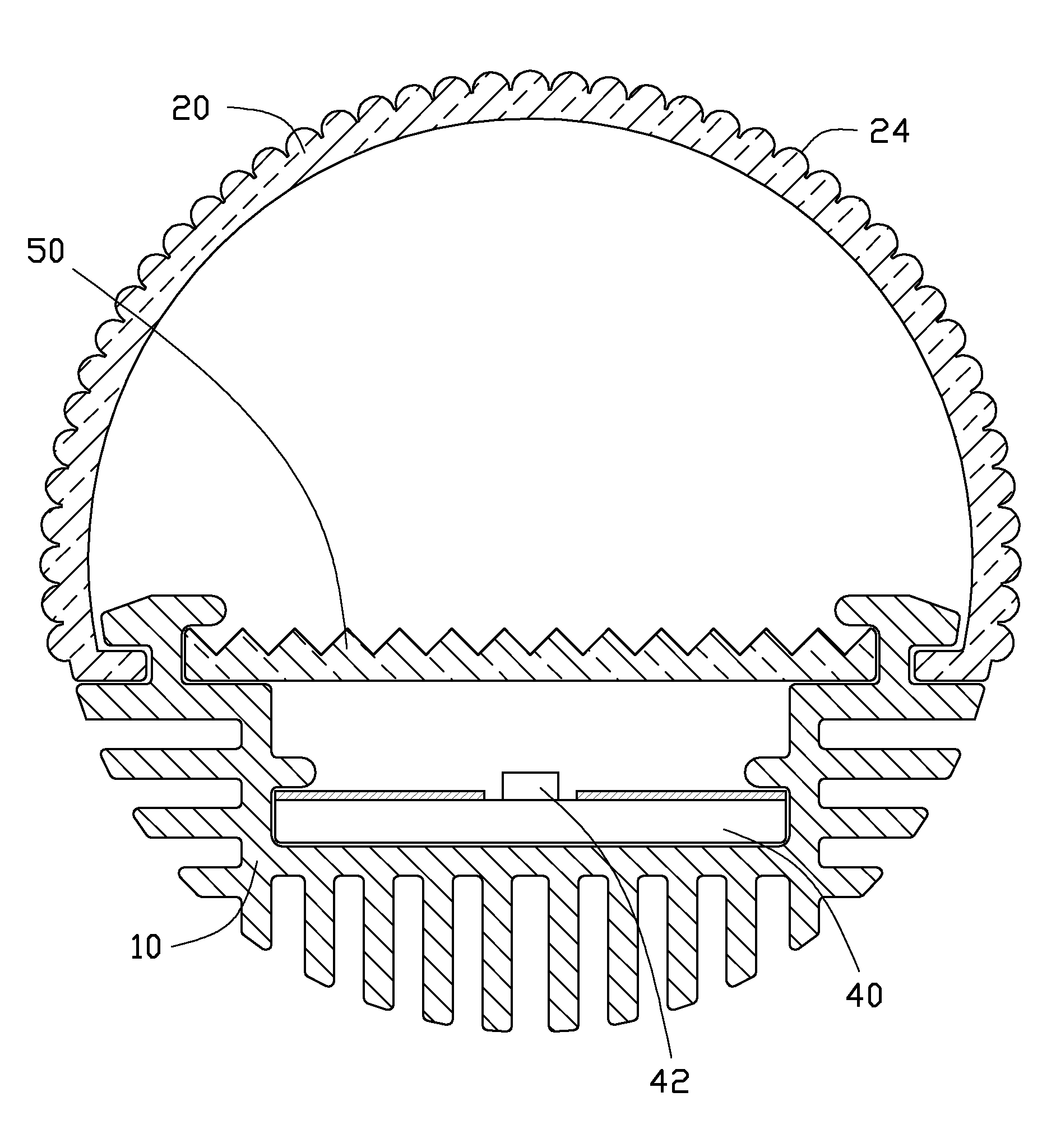
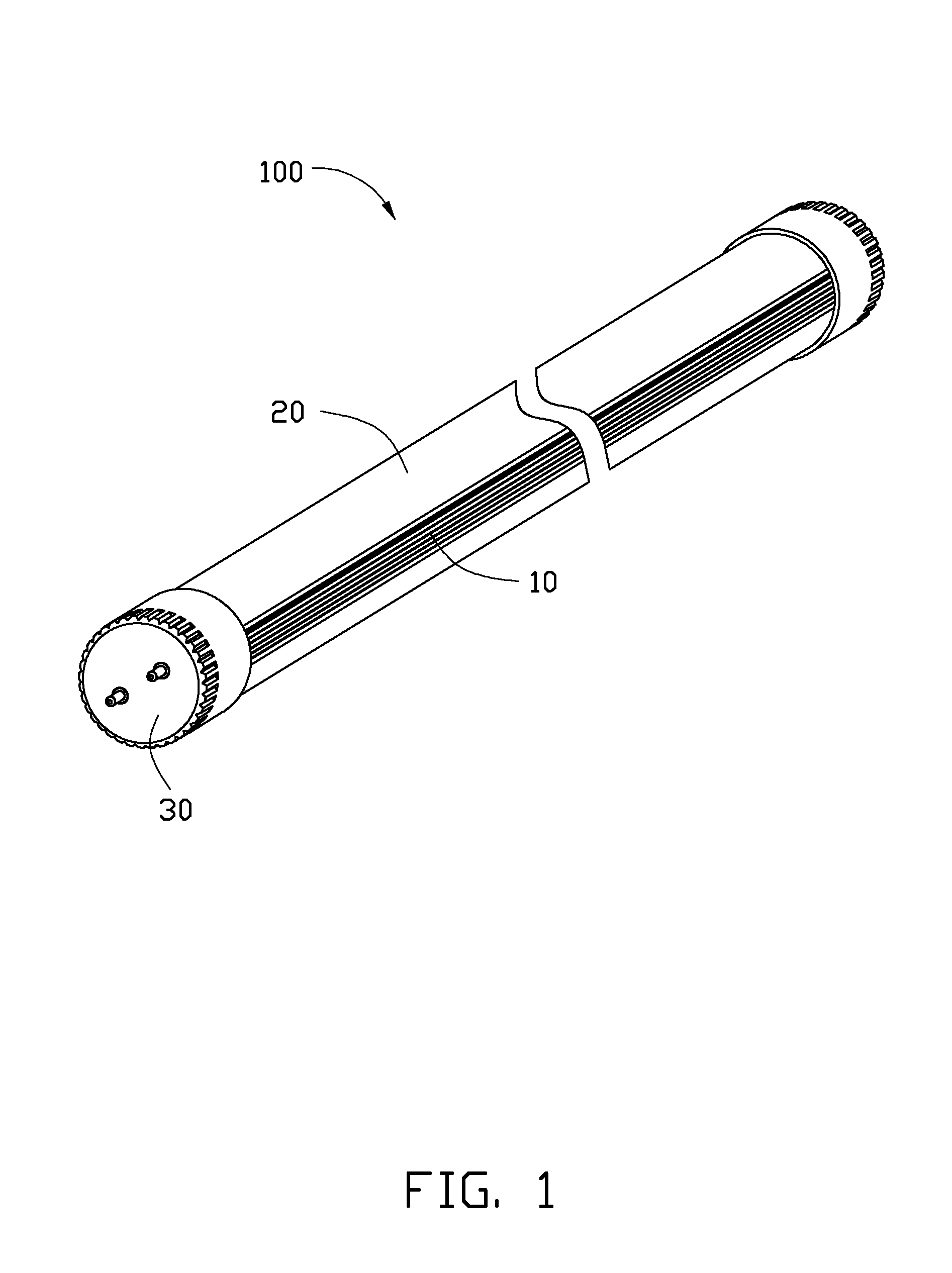
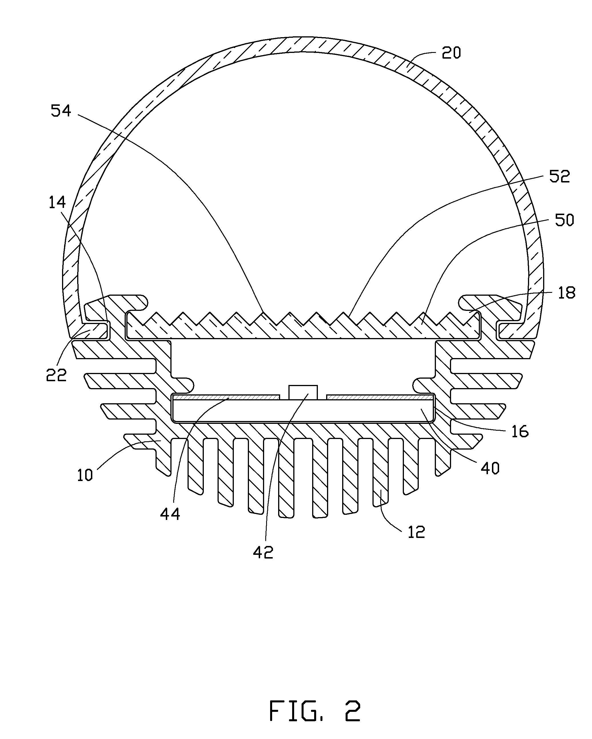
[0011]Referring to FIGS. 1 and 2, an LED lamp 100 according to an exemplary embodiment includes a base 10, a encapsulation 20, a pair of power connectors 30, a substrate 40, and a light distribution board 50. The encapsulation 20, the substrate 40 and the light distribution board 50 are all fixed to the base 10. The pair of power connectors 30 are respectively fixed to two ends of the encapsulation 20 and used to connect with a counter power connector (not shown), such that power can be supplied to the LED lamp 100. The substrate 40 is electrically connected to the power connectors 30. A number of light emitting diodes 42 are mounted on the substrate 40. The light distribution board 50 is configured for changing the direction of light beams from the emitting diodes 42.

[0012]The base 10 can be made of aluminum alloy with excellent thermal diffusivity and used for dispersing heat generated by the LED lamp 100 at work. The bottom of the base 10 includes a plurality of heat sinks 12 at ...


PUM


Abstract

An LED lamp includes a base, an encapsulation, a substrate and a light distribution board. A number of light emitting diodes are mounted on the substrate. The encapsulation, the substrate and the light distribution board are all fixed to the base. Opposite sides of the light distribution board respectively face the encapsulation and the substrate. The light distribution board includes a number of protrusions. The protrusions totally reflect the incident light beams from the light emitting diodes perpendicular to or substantially perpendicular to the light distribution board.

Description

BACKGROUND[0001]1. Technical Field[0002]The present disclosure relates to illumination devices, especially to an LED lamp.[0003]2. Description of Related Art[0004]Compared to traditional light sources, light emitting diodes (LEDs) have many advantages, such as high luminous efficiency, low power consumption, and long service life. LED lights are widely used in many applications. The light emitting diodes are small and have a narrow light emitting angle, thus the light emitting diodes emit light that may be too bright, which may negatively impact people's eyes.BRIEF DESCRIPTION OF THE DRAWINGS[0005]Many aspects of the embodiments can be better understood with reference to the following drawings. The components in the drawings are not necessarily drawn to scale, the emphasis instead being placed upon clearly illustrating the principles of the embodiments. Moreover, in the drawings, like reference numerals designate corresponding parts throughout the several views.[0006]FIG. 1 is an is...

Claims


Application Information

Patent Timeline
Patent Type & Authority Patents(United States)
IPC IPC(8): F21S4/00F21V21/00
CPCF21K9/17F21V5/02F21V7/0091F21V13/04F21V29/2212F21V29/89F21V29/713F21Y2103/003F21V29/75F21V29/763F21V29/767F21Y2101/02F21K9/27F21Y2103/10F21Y2115/10F21K9/69F21V29/76
Inventor CHANG, SHAO-HAN
Owner HON HAI PRECISION IND CO LTD
Why Eureka
Try Eureka