Method for the continuous implementation of polymerisation processes

a technology of polymerization and process, applied in the direction of clay mixing apparatus, transportation and packaging, prosthesis, etc., can solve the problems of lump formation, inability to process products, and finally inability of the stirrer to achieve sufficient convective flow

Active Publication Date: 2013-02-19
LIST TECHNOLOGY AG +1
View PDF18 Cites 6 Cited by
  • Summary
  • Abstract
  • Description
  • Claims
  • Application Information

AI Technical Summary

Benefits of technology

[0015]it is possible to work with a very small solvent excess, if any, typically <20% of the reaction mixture, and at viscosities which are 5×10⁴-5×10⁶ higher than in the stirred tank, i.e. the unpopular mechanical / thermal solvent removal process step can be eliminated,
[0021]It has been found that both homo- and copolymerization reactions can be performed successfully in mixing kneaders with residence times of >5 minutes in the highly viscous phase, i.e. with very little solvent (<20%), if any, up to a conversion of 80 to 95%, in which the monomer(s), catalysts, initiators, etc. are added continuously to a backmixed mixing kneader and backmixed therein with the already reacted product, and the reacted product is simultaneously drawn off continuously from the mixing kneader.
[0025]All, both the dynamic and the static, mixing and kneading elements are self-cleaning, have close clearance and prevent dead unmixed zones through their arrangement and design.

Problems solved by technology

The problem of these stirred tank reactors consists in the fact that it is only possible to process products with a low apparent viscosity.
With rising concentration of the polymer in the solvent / diluent, the apparent viscosity of the reaction mixture rises such that the stirrer finally cannot reaction mixture rises such that the stirrer finally cannot achieve sufficient convective flow.
This leads to lump formation, poor molar mass distribution, caking, local overheating, up to and including an uncontrolled reaction of the entire reactor contents.
A further problem of stirred tank reactors is foam formation in the case of individual products, which can lead to blockages in the vapor draws.
The above-mentioned process risks lead to the fact that stirred tank reactors are operated with a large excess of solvents / diluents up to approx.
They mean high capital, energy and operating costs.
a) In the case of slow polymer reactions with reaction times of >5 minutes, in which the reaction mixture remains in the liquid state for a long period, the plug flow cannot be maintained. The very different rheological properties between the monomers and polymers prevent uniform product transport, which leads to undesired quality variations.
b) The high exothermicity of many polymerization processes and the dissipated kneading energy frequently make it necessary to remove these energies by means of evaporative cooling. This is done by evaporating a portion of the monomer or of an added solvent / diluent, condensing it in an external condenser and recycling the condensate into the reactor. Owing to the large L / D ratio and the large screw cross section for construction reasons, only very limited free cross-sectional areas are available for the removal of vapors. This leads to the undesired entrainment of polymers into the vapor lines and into the reflux condenser and, as a consequence thereof, to blockages.
c) In the preparation of (co)polymers from a plurality of different monomers, an additional complicating factor is that mainly the monomer with the lowest boiling point evaporates for the evaporative cooling, so that a shift in the monomer concentrations is established in the reactor, especially in the region of the entry orifice of the condensate reflux. This is generally undesired.
d) Another disadvantage is that the free product volume of screws is limited to about 1.5 m3 for mechanical construction reasons, so that only low throughputs can be achieved in reactions with residence times of >5 minutes, which requires the installation of a plurality of parallel lines with correspondingly higher capital and operating costs.
However, the above-described problems b) (reduced free cross section) and d) (size) still remain unsolved.

Method used


Image

  • Method for the continuous implementation of polymerisation processes
  • Method for the continuous implementation of polymerisation processes
  • Method for the continuous implementation of polymerisation processes

Examples


example 1

[0047]Continuous bulk polymerization of MMA above the glass transition temperature (novel process).

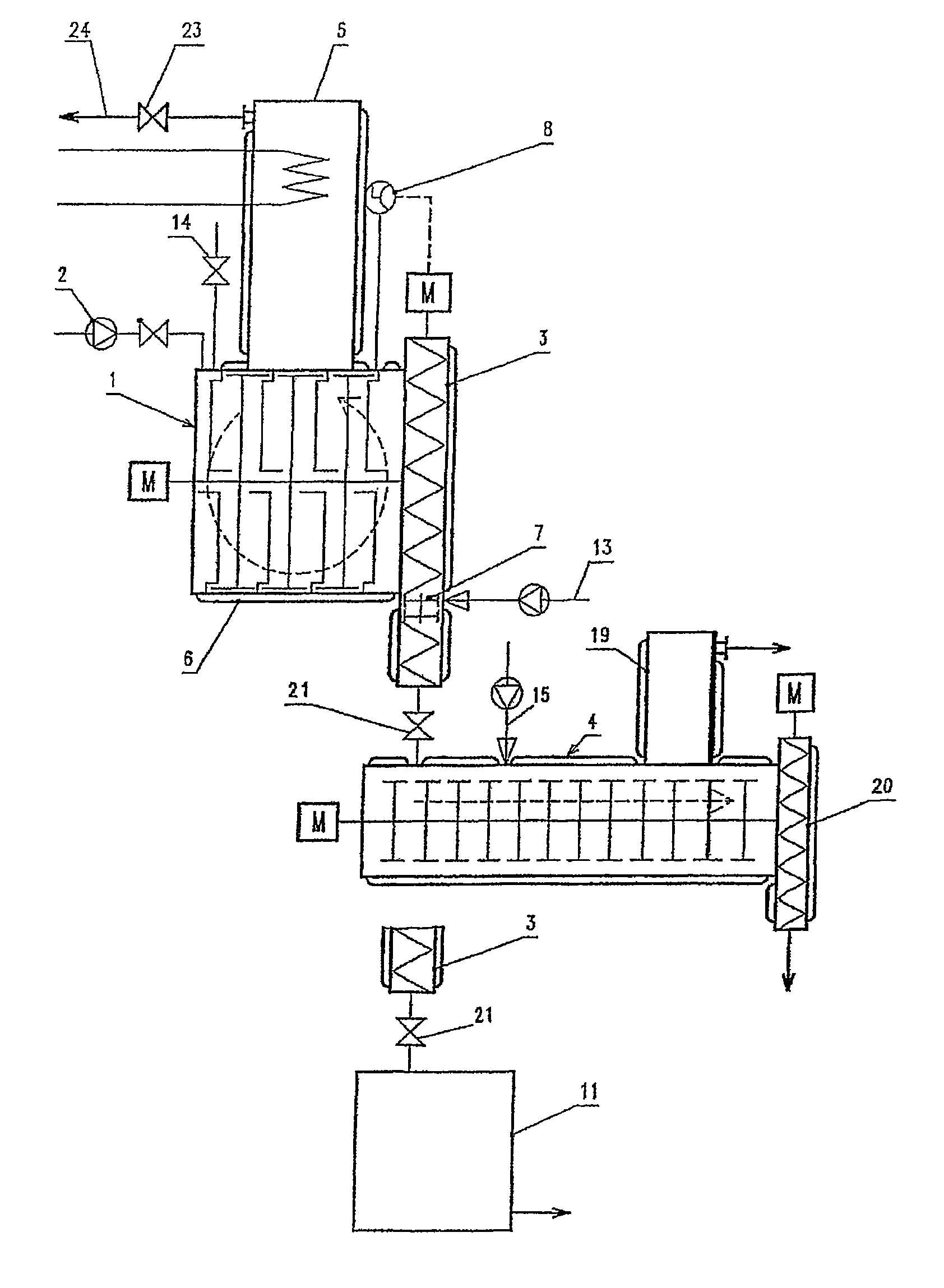
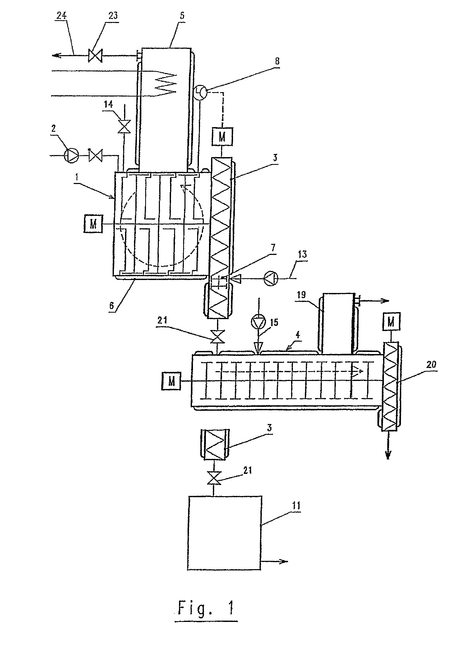
[0048]The backmixed LIST kneading reactor 1-1.2 has a total volume of 6 liters, and the casing is heated with an inlet temperature of 145° C. A cooled dome, wall temperature 15° C., which condenses the monomer vapors back into the process space, is disposed on the kneading reactor. A discharge twin screw (3-3.2) is mounted on the end side of the reactor (1-1.2) and discharges the polymer mixture with the same throughput as the monomer stream metered in. The jacket of the discharge twin screw (3-3.2) is heated to 210° C. A heated valve is installed downstream of the discharge twin screw, in order to ensure that the system is leakproof for the startup. The monomer feed tank and the kneading reactor are inertized with nitrogen (N2) before startup. The internal pressure in the reactor is adjusted to 3.5 bar absolute with inert gas (N2). The monomer metering is envisaged with a monomer tank...

example 2

[0056]EP 0 209 253 A1 (manufacture of butyl rubber) discloses a continuous polymerization process of butyl rubber in an extruder. Here, the monomers are polymerized in a halogenated polymerization medium at constant pressure under boiling conditions with plug flow, using a modified aluminum catalyst. This converts the nonviscous monomer to a viscous tacky polymer with advancing reaction.

[0057]It has been found that, owing to the huge viscosity difference between monomer and polymer, the desired plug flow in the extruder cannot be maintained because the large content of nonvolatile monomer undermines the plug flow and prevents the product transport based on the shear gradient in the reactor. This leads to the fact that it is virtually impossible to obtain uniform product transport and hence homogeneous conversion rates.

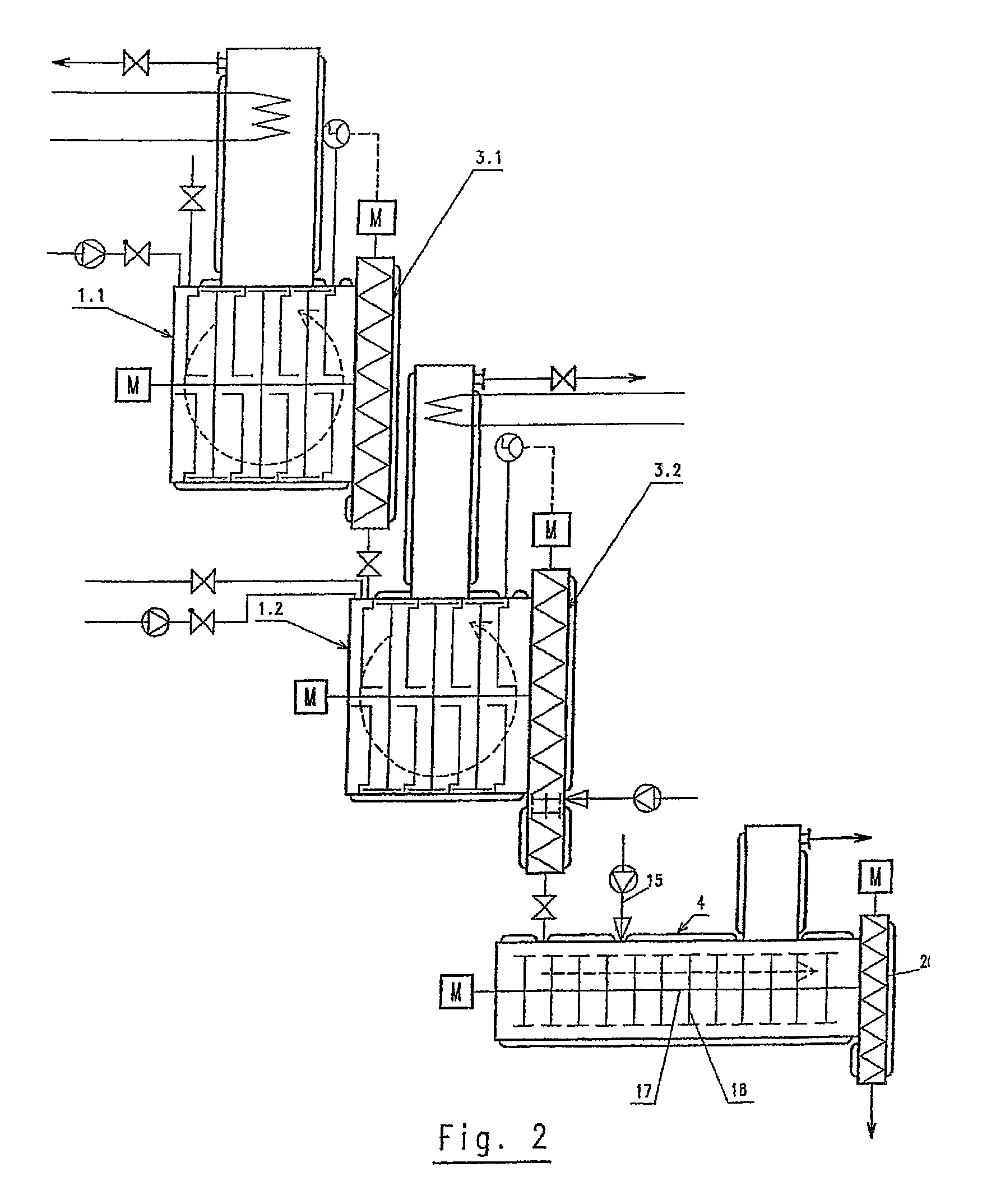
[0058]In the case of use of a backmixed mixing kneader 1-1.3 according to the present invention, this problem can be avoided elegantly, since the comparatively small a...


PUM

PropertyMeasurementUnit
volumeaaaaaaaaaa
temperatureaaaaaaaaaa

Abstract

A process for continuously performing polymerization processes, wherein monomer(s), catalysts, and initiators are added continuously to a backmixed mixing kneader (1-1.3) with a length / diameter ratio of 0.5-3.5 and backmixed therein with already reacted product, and the reacted product is simultaneously drawn off continuously from the mixing kneader (1-1.3).

Description

BACKGROUND OF THE INVENTION[0001]The invention relates to a process for continuously performing polymerization processes, especially for the homo- or copolymerization of thermoplastics and elastomers, and a system therefore.[0002]A considerable portion of polymerization reactions, especially for the preparation of homo- and copolymeric thermoplastics and elastomers, are performed commercially as a slurry or solution process in one or more series-connected, continuous, backmixed, vertical stirred tank reactors, known as “CSTRs”, continuous stirred tank reactors.[0003]These stirred tank reactors have the task of very homogeneously distributing the monomers, catalysts and initiators in a solvent / diluent under precisely defined process conditions, such as temperature and pressure, in order that the reaction proceeds in a controlled manner, a uniform product quality with the desired molar mass is formed and the heat of reaction is also controlled.[0004]The problem of these stirred tank r...

Claims


Application Information

Patent Timeline
Patent Type & Authority Patents(United States)
IPC IPC(8): A21C1/00B01F7/00A61F2/00A61F2/50A61F2/60A61F2/66A61F2/76
CPCB01F5/104B01F7/048B01F13/1027B01F15/0289B01J8/10B01J19/0066C08F2/02B01J2219/00033B01J2219/0004B01J2219/00108B01J2219/00128B01J2219/00168B01J2219/0025B01J2219/00272B01J2219/182B01F25/52B01F27/707B01F33/821B01F35/754551
Inventor FLEURY, PIERRE-ALAINISENSCHMID, THOMASLIECHTI, PIERRE
Owner LIST TECHNOLOGY AG
Why Eureka
Try Eureka