
Systems and methods to generate propulsor side forces

a propulsor and side force technology, applied in the field of underwater vehicle maneuvering force generation, can solve the problems of reducing the effectiveness of tunnel thrusters, reducing methods, and only achieving twenty percent effective tunnel thrusters above five knots, so as to enhance maneuvering forces and optimize rotor forces

Inactive Publication Date: 2013-02-19
THE UNITED STATES OF AMERICA AS REPRESENTED BY THE SECRETARY OF THE NAVY
View PDF4 Cites 3 Cited by
  • Summary
  • Abstract
  • Description
  • Claims
  • Application Information

AI Technical Summary

Benefits of technology

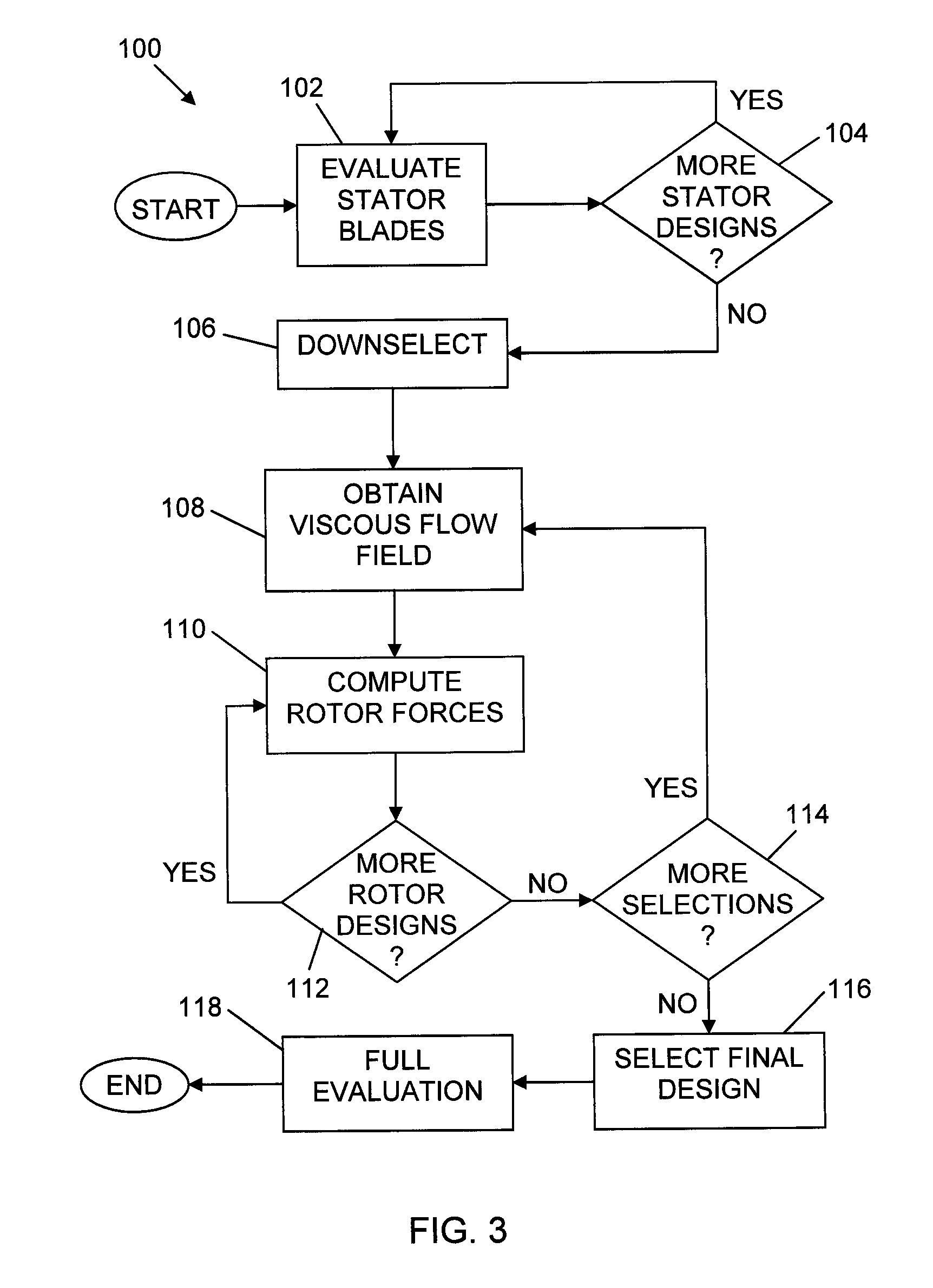
The patent text describes a method for designing a ducted, pre-swirl propulsor for an underwater vehicle to produce maneuvering forces. The method involves characterizing the stator-induced flow and computing rotor forces based on the induced flow. By optimizing the rotor forces and combining them with flow-induced stator forces, enhanced maneuvering forces can be achieved. The choice of rotor blade parameters can involve selecting a combination of two or more of the number of rotor blades, the rotor blade skew, and the rotor blade rake to maximize the mean rotor forces and minimize the unsteady rotor forces.

Problems solved by technology

The difficulty is that this method is most effective at zero speeds.
As the flow velocity is increased, tunnel thruster effectiveness is significantly diminished.
It has been shown that tunnel thrusters are only twenty percent effective above five knots.
In addition, tunnel thrusters take up considerable volume that could otherwise be used for energy or payload.
The disadvantage is that the Haselton bow propulsor concept remains mechanically complex for implementation on undersea vehicles.
In addition, placing a propulsor at the bow of the vehicle interferes with forward looking sonar systems.

Method used


Image

  • Systems and methods to generate propulsor side forces
  • Systems and methods to generate propulsor side forces
  • Systems and methods to generate propulsor side forces

Examples


Embodiment Construction

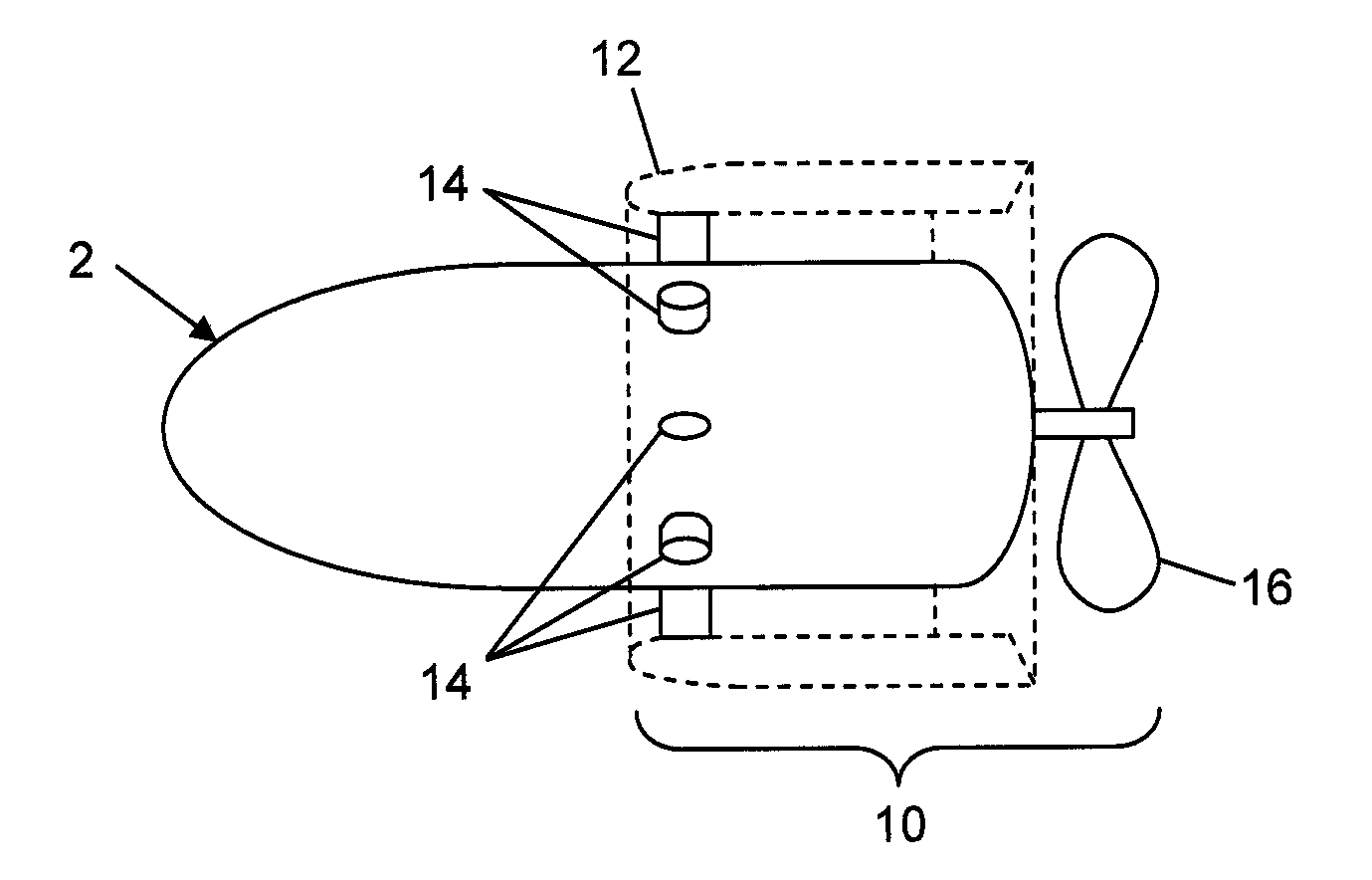
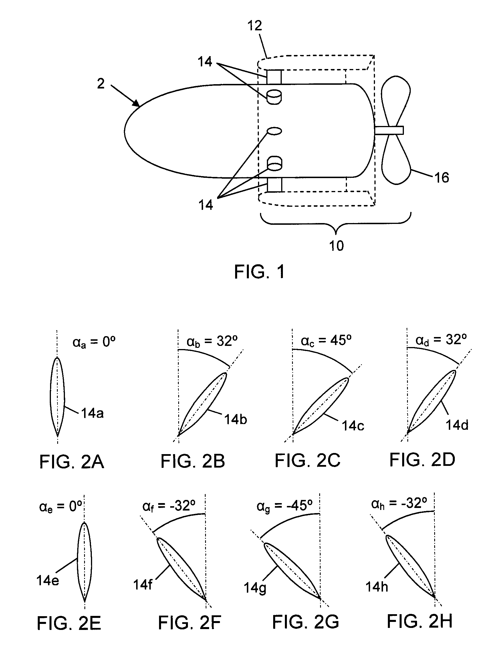
[0031]Referring to FIG. 1, there is shown a side view of an underwater vehicle 2 in which the vehicle has a ducted pre-swirl propulsor 10. For clarity of illustration, duct 12 of the propulsor 10 is shown in phantom. During normal operation and in prior art designs, upstream stator blades 14 are situated at the same pitch angle, or angle of attack, and pre-swirl a flow towards rotor 16 of the propulsor 10. As is known to those of skill in the art, pre-swirling the flow results in generating a roll moment which counters the moment produced by rotor 16.

[0032]For the propulsor 10 to generate vehicle maneuvering forces, the upstream stator blades 14 are situated at varying pitch angles. As will be explained in further detail hereinafter, calculations indicate that this variation in pitch angle results in the upstream stator blades 14 generating a stator side force. Further, the variation in pitch angle also introduces a circumferentially varying downwash that is ingested into the rotor ...


PUM


Abstract

Systems and methods for maneuvering an underwater vehicle by generating vehicle maneuvering forces from a propulsor of the vehicle are provided. A ducted, pre-swirl propulsor is configured such that the pitch angles of the stator blades of the upstream stator row can be varied. By varying the pitch angles of the stator blades about the circumference, a mean stator side force is generated. Subsequently, the axial velocity and swirl that is ingested into the inflow is varied. The rotor of the propulsor then generates a side force in response to the inflow.

Description

CROSS REFERENCE TO OTHER PATENT APPLICATIONS[0001]This application claims the benefit of U.S. Provisional Patent Application No. 61 / 202,589 filed on Mar. 13, 2009 and entitled “A Method to Generate Propulsor Side Forces” by the inventors, David N. Beal and Stephen A. Huyer.STATEMENT OF GOVERNMENT INTEREST[0002]The invention described herein may be manufactured and used by or for the Government of the United States of America for governmental purposes without the payment of any royalties thereon or therefor.BACKGROUND OF THE INVENTION[0003](1) Field of the Invention[0004]The present invention relates to maneuvering an underwater vehicle, and more specifically to systems and methods for generating vehicle maneuvering forces from a propulsor.[0005](2) Description of the Prior Art[0006]Standard torpedoes and Unmanned Undersea Vehicles (UUVs) utilize a single propulsor at the stern coupled with control surfaces to provide the vehicle with necessary forces and moments to offer control. At...

Claims


Application Information

Patent Timeline
Patent Type & Authority Patents(United States)
IPC IPC(8): B63H5/04
CPCB63H5/04
Inventor BEAL, DAVID N.HUYER, STEPHEN A.
Owner THE UNITED STATES OF AMERICA AS REPRESENTED BY THE SECRETARY OF THE NAVY
Learn More