Eureka AIR delivers breakthrough ideas for toughest innovation challenges, trusted by R&D personnel around the world.

Cyclonic dust collector with vee-shaped cyclone

a cyclone and dust collector technology, applied in the field of dust collection systems, can solve the problems of high pressure and velocity, unfavorable dust separation, and poor design or undersized dust ports of manufacturers, and achieve the effects of improving dust separation, improving dust separation, and improving performance and separation

Active Publication Date: 2013-02-19
ONEIDA AIR SYST
View PDF2 Cites 14 Cited by
  • Summary
  • Abstract
  • Description
  • Claims
  • Application Information

AI Technical Summary

Benefits of technology

[0019]It is an object of this invention to provide a dust collection system that avoids the drawbacks of the prior art, as mentioned just above.
[0020]It is one particular object to provide a dust collection system in which the air flow adjusts automatically in response to changes in demand and to changes in the air flow impedance from the dust-producing tools and ductwork, to maintain the separator system at an optimum efficiency.

Problems solved by technology

In some cases, flammable process dust is generated and can create risk of fire or explosion.
Furthermore, it is not uncommon for manufacturers to have poorly designed or undersized dust ports integrated into the machine, requiring much higher pressures and velocities than is recommended to meet the best-practice standard.
However, at present it has not been possible to automatically adjust motor speed to accommodate changing conditions.
Problems exist in the current state of the art where a dust collection radial fan blower, of the type used in material conveying systems, delivers a pressure-to-volume characteristic that is a well-defined single function or curve on a X-axis / Y-axis chart, considered where impeller speeds are constant.
The drawbacks of this design are numerous, as the air flow demand can easily go outside the design airflow band of the blower.
Also, any addition of ductwork or dust conduit reduces the work efficiency of the system.
System air friction, i.e., air handling losses, increase with longer duct runs, multiple branches, transitions, elbows, smaller dust inlet ports, flexible hose, loading pressure losses across the filter media, and other restrictions.
Because of these impairments to air flow, the fan air flow performance is reduced and the work capacity of the system is decreased.
Any increase in pipe length or decrease of pipe diameters will result in increased friction loss and reduced airflow.
The resulting drop in flow efficiency decreases the amperage draw and this reduces the output power available from the motor.
The reduced heat of combustion extinguishes the flame from a deflagration, not allowing it to exit the device where it could ignite a secondary deflagration.
Dust collection systems that experience this type of upset can explode unless adequately protected or vented to atmosphere.
This can be very expensive and complex, requiring gates, dampers, and / or abort gates that have to be timed electronically to actuate within small fractions of a second.
Cyclone systems are particularly difficult to adapt to the conventional technique because the flame from a deflagration must be diverted, but at the same time the outlet flow from the system must be simultaneously blocked off.
Conventional anti-deflagration systems require complex and expensive sensors and controls, with elaborate engineering control equipment.

Method used


Image

  • Cyclonic dust collector with vee-shaped cyclone
  • Cyclonic dust collector with vee-shaped cyclone
  • Cyclonic dust collector with vee-shaped cyclone

Examples


Embodiment Construction

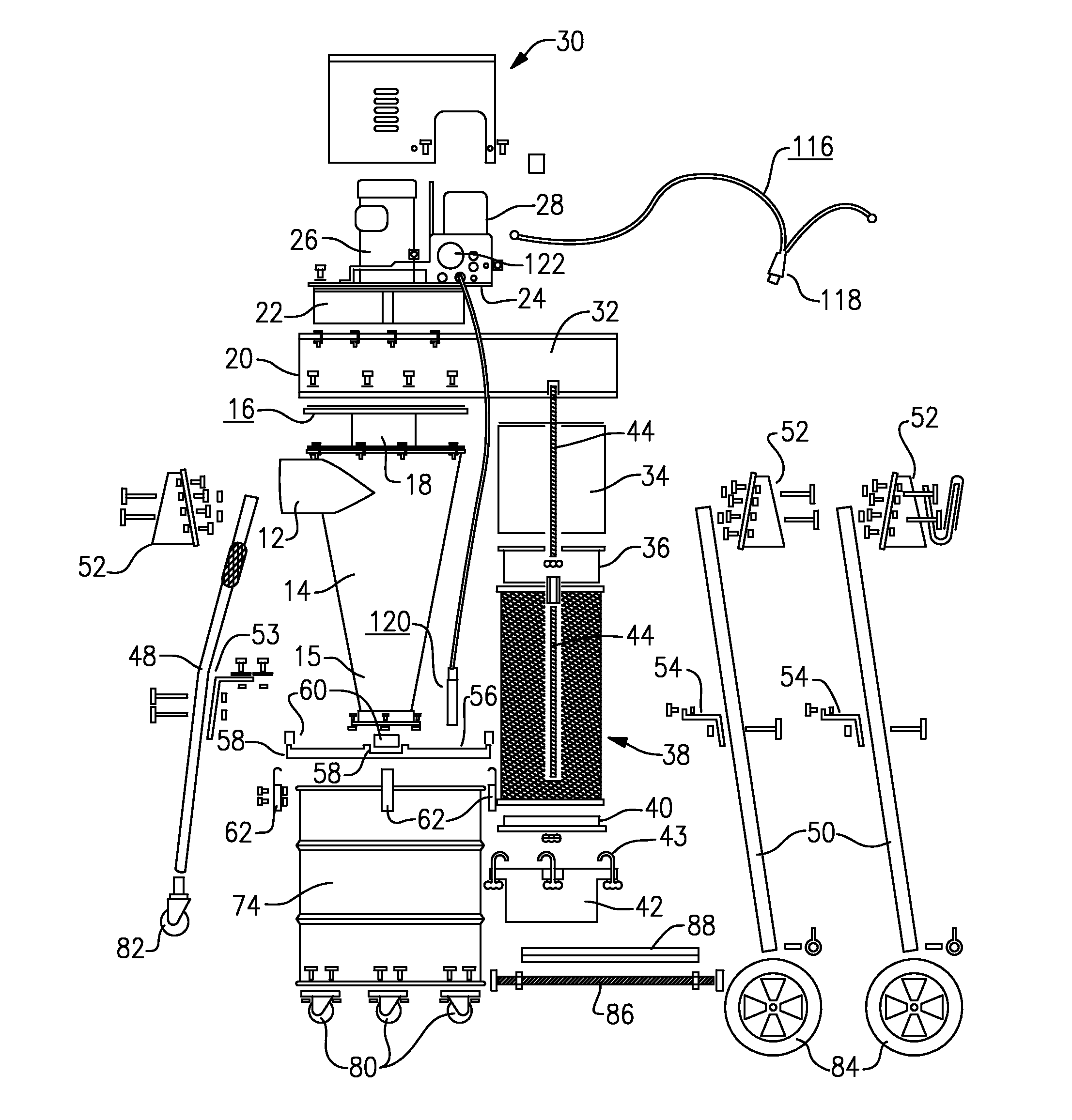
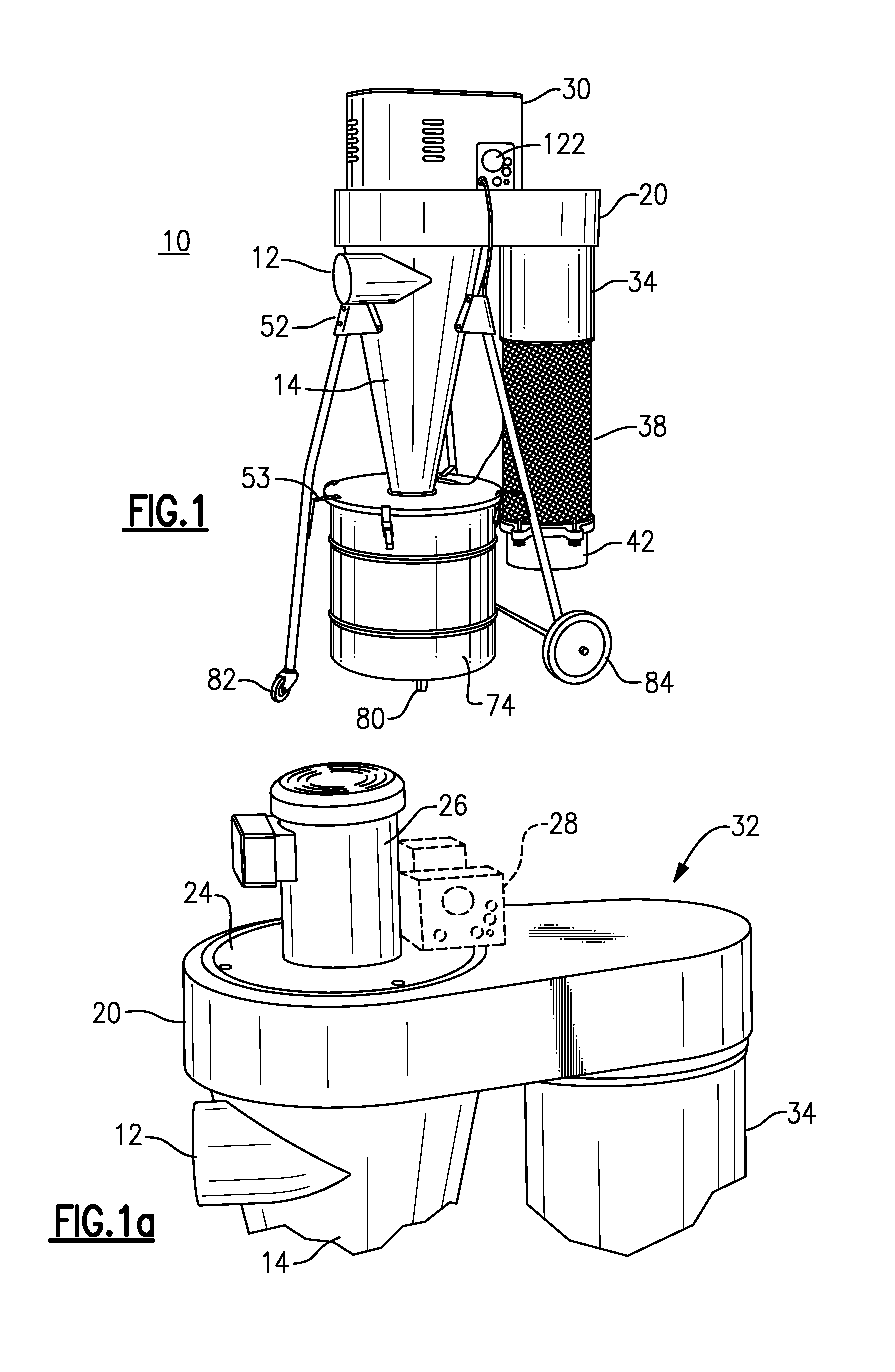
[0053]With reference to the Drawing, and initially to FIGS. 1, 1a, and 2, a portable cyclonic dust collector 10 is provided with an intake duct 12 that penetrates a conic separator body 14 which is of a conic shape, and having a conic wall that extends from a lower nose 15 to a divider plate 16 (shown in FIG. 4) at the top of the conic wall, so that a cyclonic separation chamber is defined within the conic body between to lower nose 15 and the upper or divider plate 16. A vortex tube 18 descends from a central opening of the divider plate 16 for a distance into the cyclonic separation chamber.

[0054]A fan housing 20 is situated above the conic body 14, and contains a rotary radial fan 22 with a vertical axis centered on the axis of the body 14 and vortex tube 18. A motor plate 24 closes off the top of the fan housing 20, and supports a vertical-shaft drive motor 26 for the fan 22, which in a preferred embodiment is a three-phase AC induction motor. A motor drive circuit 28, as explai...


PUM

PropertyMeasurementUnit
apex angleaaaaaaaaaa
concentrationaaaaaaaaaa
frequencyaaaaaaaaaa

Abstract

A cyclonic dust collector arrangement employs a cyclone that has a conic body formed of a conic wall. An upper divider plate closes off the upper end of the conic body, with a vortex tube descending from a central passage in the divider plate. The conic body has a narrow nose at a lower end so that the upper divider plate and the lower nose define a cyclonic chamber within the conic body. The inlet conduit penetrates the conic wall below the divider plate. The fan chamber of the separator is mounted above the divider plate, and serves to induce air flow from the inlet conduit into the cyclonic chamber, and through said vortex tube into the fan chamber. The air is discharged through a final filter. This construction has reduced manufacture costs and improved dust separation.

Description

[0001]This application claims priority under 35 U.S.C. 119(e) of Provisional Pat. Applns. 61 / 306,056, filed Feb. 19, 2010 and 61 / 315,695, filed Mar. 19, 2010. The disclosure therein is incorporated here by reference.BACKGROUND OF THE INVENTION[0002]This invention is directed to a dust collection system as used in cabinetmaking, carpentry and similar trades, or in any industrial setting in which process dust is generated and needs to be controlled. In some cases, flammable process dust is generated and can create risk of fire or explosion. In the dust collection system, the process dust is directed from dust producing equipment to a dust storage drum and the airflow is separated from the dust is returned to the ambient. In favorable embodiments, the dust collection system may involve a cyclonic dust separator, followed by a HEPA filter or similar final air filter.[0003]The invention is more specifically directed to a dust separator in which the motor that drives the blower or impelle...

Claims


Application Information

Patent Timeline
Patent Type & Authority Patents(United States)
IPC IPC(8): B01D50/00
CPCB01D46/0093B01D46/42
Inventor WITTER, ROBERT M.
Owner ONEIDA AIR SYST
Why Eureka
Eureka Blog
Learn More