Gas sensor control device and gas sensor control method

a control device and sensor technology, applied in the direction of instruments, liquid/fluent solid measurement, electrochemical variables, etc., can solve the problems of gas sensor wiring anomalies, excessive current flows, gas sensor breakage, etc., to suppress useless electrical power consumption and prevent gas sensor breakage

Active Publication Date: 2013-02-19
NGK SPARK PLUG CO LTD
View PDF9 Cites 6 Cited by
  • Summary
  • Abstract
  • Description
  • Claims
  • Application Information

AI Technical Summary

Benefits of technology

[0015]In view of the foregoing, an object of the present invention is to provide a gas sensor control apparatus which can accurately determine whether or not a wiring anomaly has occurred in a sensor drive circuit or a gas sensor, and which does not require wasteful time to return to gas-concentration-measurement operation after the wiring anomaly disappears.Means for Solving the Problems
[0017]The gas sensor control apparatus having the above-described configuration operates as follows. Even when the gas sensor control apparatus detects a wiring anomaly once, the sensor control apparatus does not immediately stop the operation of the gas sensor by finally determining that the wiring anomaly has occurred. Instead, the gas sensor control apparatus causes the sensor drive circuit to return to the energization state and then again determines whether or not the wiring anomaly is present. Thus, it becomes possible to prevent erroneous detection of a wiring anomaly and prevent the operation of the gas sensor from being stopped meaninglessly when the wiring anomaly disappears immediately.
[0021]According to this configuration, during a period between a point in time at which a wiring anomaly is first detected and a point in time at which the final determination is made as to whether the wiring anomaly has occurred, the heater is suitably energized at an intermediate voltage by use of the heater control circuit, which energizes and controls the heater for heating the cell to the activation temperature or higher. Therefore, in the case where the gas sensor stops the ordinary operation (the gas-concentration-measurement operation) upon detection of a temporary wiring anomaly and then resumes the ordinary operation (the gas-concentration-measurement operation) because of the final determination that a wiring anomaly has not occurred, the gas sensor can be prevented from cooling down. Therefore, the sensor can quickly resume the ordinary operation. Meanwhile, in some cases, a detected wiring anomaly is finally determined to have occurred. If the heater is energized at the maximum voltage in such a case, electrical power is uselessly consumed. However, in the present invention, since the heater is energized at an intermediate voltage, the power consumption can be reduced.
[0023]According to this configuration, the heater is deenergized after the anomaly is finally determined to have occurred (hereinafter referred to as “anomaly final determination”). Therefore, it is possible to prevent breakage of the gas sensor due to an excessive temperature increase, which would otherwise occur when heating of the cells (gas sensor) by the heater is continued after the anomaly final determination, and to suppress useless consumption of electrical power.

Problems solved by technology

Incidentally, the sensor drive circuit or wiring lines (electricity supply lines) of the gas sensor may suffer a wiring anomaly, such as wire breakage or short-circuiting with a battery or the ground.
When, irrespective of occurrence of such a wiring anomaly, the energization state for gas concentration measurement is continued so as to measure the concentration of the specific gas, an excessively large current flows through the gas sensor, and the gas sensor may be broken.
Further, when an instruction for switching to the energization state for gas concentration measurement from another energization state is output to the sensor drive circuit without awareness of a wiring anomaly, similarly, an excessively large current flows to the gas sensor, and the gas sensor may be broken.

Method used


Image

  • Gas sensor control device and gas sensor control method
  • Gas sensor control device and gas sensor control method
  • Gas sensor control device and gas sensor control method

Examples


first embodiment

A. First Embodiment

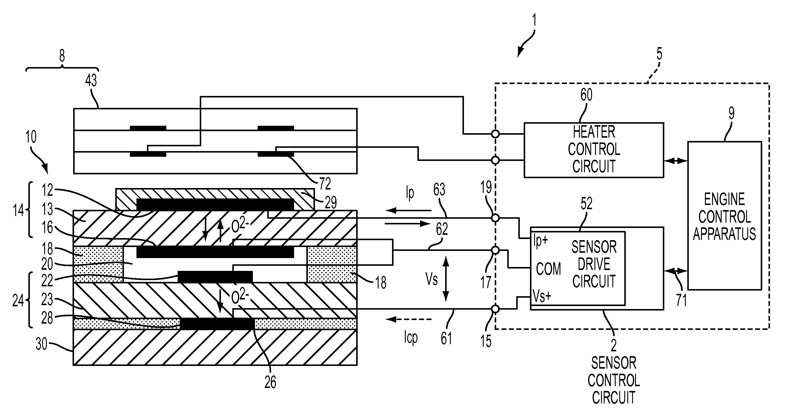
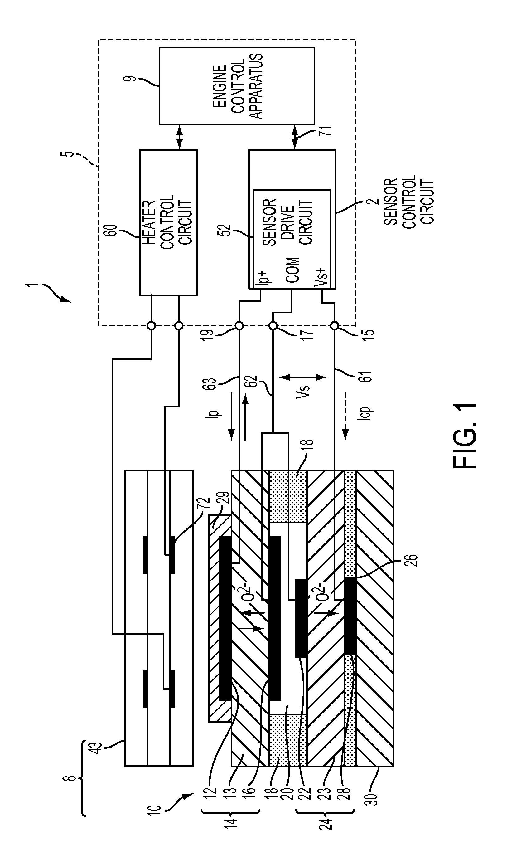
[0038]FIG. 1 is a schematic diagram showing the configuration of an internal-combustion-engine control system 1 which includes a gas sensor control apparatus (electronic control unit; ECU) 5 according to an embodiment of the present invention. Notably, the internal-combustion-engine control system 1 executes various control processings for controlling the operation state of the internal combustion engine (engine), and also executes processing for detecting the concentration of a specific gas (oxygen) contained in an object gas (exhaust gas).

[0039]The internal-combustion-engine control system 1 includes an electronic control unit 5 and a gas sensor 8, which is attached to an exhaust pipe of the engine. The electronic control unit 5 includes a sensor control circuit 2 which controls the gas sensor 8 (a sensor element 10), an engine control apparatus 9 (hereinafter, also referred to as the “engine CPU”9), and a heater control circuit 60 which controls a heater 43. Th...

second embodiment

B. Second Embodiment

[0135]FIG. 5 is a flowchart showing anomaly final determination processing according to a second embodiment of the present invention, which is executed in an internal-combustion-engine control system including a gas sensor control apparatus. The internal-combustion-engine control system according to the second embodiment differs from the internal-combustion-engine control system 1 of the first embodiment in the details of the anomaly final determination processing, and is identical with the internal-combustion-engine control system 1 of the first embodiment in the remaining software configuration and the hardware configuration. This anomaly final determination processing corresponds to the anomaly final determination processing of the first embodiment shown in FIG. 4, but additionally includes processing for energization control of the heater 43 by the heater control circuit 60.

[0136]As in the case of the first embodiment, the anomaly final determination processi...


PUM

PropertyMeasurementUnit
temperatureaaaaaaaaaa
electromotive forceaaaaaaaaaa
voltageaaaaaaaaaa

Abstract

A gas sensor control apparatus 5 is connected to a gas sensor (8) including cells (14, 24) each having a pair of electrodes provided on a solid electrolyte body (13, 23), and includes a sensor drive circuit (52). The gas sensor control apparatus (5) includes an instruction unit for outputting an instruction for setting the sensor drive circuit (52) to a deenergization state so as to stop the supply of electricity to the cells (14, 24) and an instruction for setting the sensor drive circuit (52) to an energization state so as to supply electricity to the cells (14, 24); a setting unit (55) for setting the sensor drive circuit (52) to the deenergization state or the energization state; and a wiring anomaly detection unit (58) for detecting a wiring anomaly of the sensor drive circuit (52) or the gas sensor (8). The gas sensor control apparatus (5) further includes an anomaly final determination unit, operable when a wiring anomaly is detected, for performing return-from-anomaly checking processing so as to cause the instruction unit to output the deenergization instruction and then output the energization instruction.

Description

TECHNICAL FIELD[0001]The present invention relates to a sensor control apparatus and a sensor control method for controlling the energization state of a gas sensor including at least one cell which includes a solid electrolyte body and a pair of electrodes provided on the solid electrolyte body.BACKGROUND ART[0002]An oxygen sensor, which detects the concentration of oxygen within exhaust gas, is known as a gas sensor used for improving the fuel consumption of an internal combustion engine of an automobile or the like and / or for performing combustion control for the engine. Further, there has been demanded reduction in the amount of nitrogen oxides (NOx) within exhaust gas in order to cope with the strengthened exhaust gas regulation for automobiles, and NOx sensors which can directly measure NOx concentration have been developed.[0003]Such a gas sensor includes a gas sensor element having one or more cells each composed of oxygen-ion conductive solid electrolyte layer formed of zirc...

Claims


Application Information

Patent Timeline
Patent Type & Authority Patents(United States)
IPC IPC(8): G01N27/407
CPCG01N27/407G01N33/0037G01N33/007Y02A50/20
Inventor IEDA, NORIKAZUINOUE, YOSHINORI
Owner NGK SPARK PLUG CO LTD
Why Eureka
Try Eureka