
Current sensor

a current sensor and current technology, applied in the field of electric current sensing, can solve the problems of system inability to achieve good isolation between channels, none of the known solutions can meet all the requirements, etc., and achieve the effect of maintaining the immunity to uniform and gradient magnetic fields and improving the immunity to fields produced

Active Publication Date: 2013-02-19
SENTIC LTD
View PDF2 Cites 4 Cited by
  • Summary
  • Abstract
  • Description
  • Claims
  • Application Information

AI Technical Summary

Benefits of technology

[0017]It is therefore an object of the present invention to provide a current sensor that fulfils the above mentioned requirements and is at the same time substantially immune to signals from neighbouring conductors and / or connectors. The present invention describes a current sensor. It uses a novel planar coil structure for the measurement of the magnetic field generated by a current in a conductor in the near-field, responding to the rate of change current through said conductor. At the same time it does not respond to the field from a current in a path that is a defined distance from the centre, i.e. in a directly neighbouring conductor and sensor coil, nor to conductors and sensor coils assemblies adjacent to these, in the mid-field region. This is achieved while maintaining the immunity to uniform and gradient magnetic fields and improving immunity to fields produced by distant conductors compared to the existing art.
[0018]The invention according to preferred embodiments uses three or more dipole coil segments with co-located magnetic centres. These can be optimised to maximise the sensitivity to the local current carrying conductor. They are balanced substantially to eliminate any response to uniform and gradient magnetic fields. The choice of dipoles of appropriate areas per turn and number of turns substantially eliminates any response to conductors at known distances—typically achieving current rejection ratios of around 10000:1.

Problems solved by technology

If the device requires more than one measurement of current, the system can not achieve good isolation between channels without a significant minimum spacing between current sensors.
None of the known solutions are able to meet all of the requirements stated above, in particular the ability to place multiple sensors in close proximity with minimal interference, such as might be implemented in a polyphase electricity meter with bottom-entry current terminals, where the terminals of separate current circuits are adjacent and in close proximity.

Method used


Image

  • Current sensor
  • Current sensor
  • Current sensor

Examples


Embodiment Construction

[0050]Terminal-based polyphase electricity meters typically have three or four adjacent pairs of terminals for connection to the current circuits. These are generally arranged as equally-spaced terminals along the bottom edge of the meter, with a typical terminal pitch of 12-15 mm. Within each pair, the left-hand terminal generally connects to the line (source) and the right hand terminal connects to the load, for a particular phase. In a three-phase system, the current circuits for each phase will be adjacent to each other, and additionally a fourth pair of terminals may be present for the neutral circuit.

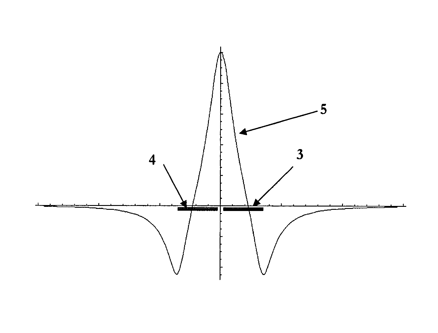
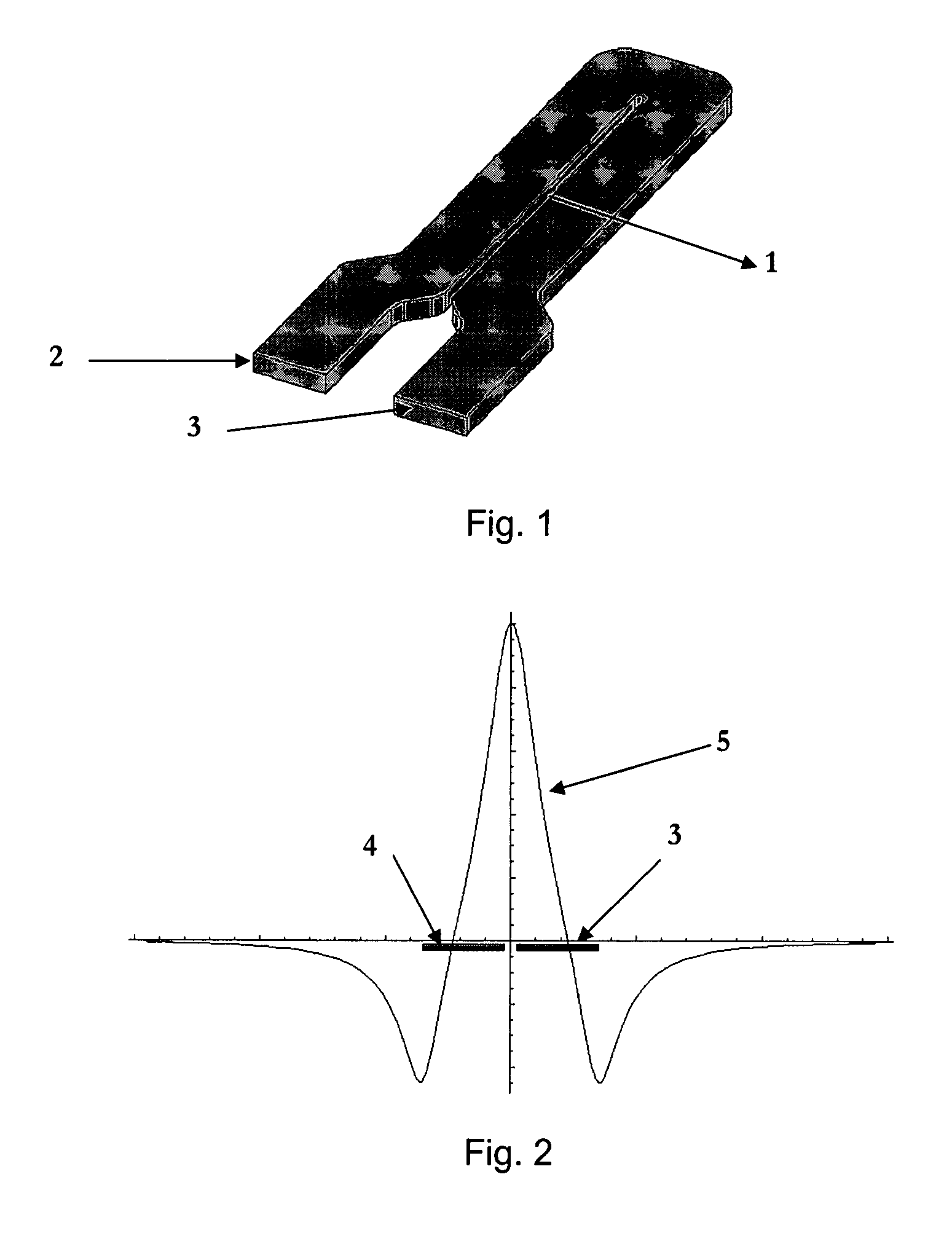
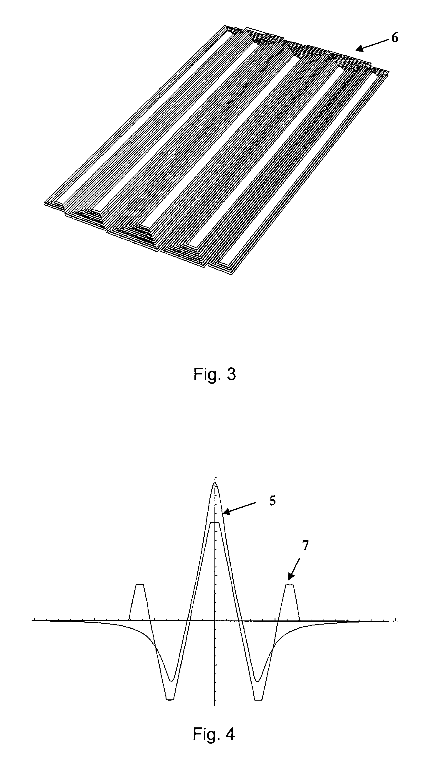
[0051]An appropriate conductor to carry the current to be measured is a hairpin shape, shown in FIG. 1. The two ends of the bus bar 2 and 3 are spaced according to the geometry of the terminals of an IEC (International Electrotechnical Commission) three phase electricity meter, where 2 is the source of the current and 3 is the load. FIG. 2 shows the magnetic field perpendicular to...


PUM


Abstract

The present invention is a current sensor architecture using a planar coils in close proximity to a current conductor to detect the rate of change of current in the conductor (and hence, by using an integrator, to recover the AC current). The current sensor is optimised to reject uniform external magnetic fields, gradient external magnetic fields, and fields from one or more conductor assemblies in fixed locations in close proximity to the current sensor, such as might be found in a polyphase electric meter with multiple current sensors.

Description

FIELD OF THE INVENTION[0001]This invention relates to the field of electrical current sensing and in particular to a sensing device for use as an AC current sensor used in fiscal electricity metering for measuring energy, current and power quality.BACKGROUND[0002]Current sensors for electricity metering are often subject to a number of requirements. These may include:[0003]1. Defined geometry of current circuit connections[0004]2. Multiple, adjacent, independent sensors, closely spaced.[0005]3. Excellent immunity to external AC field (either from nearby conductors or from attempts to tamper)[0006]4. Substantially complete immunity to DC magnetic field[0007]5. Low cost[0008]6. Wide dynamic range (typically >=1000:1)[0009]7. Good linearity (typically 0.2%)DEFINITIONS[0010]When analysing the effect of a magnetic system in free space it is useful to look at the properties of the field response of the system in different regions of space.[0011]The near-field is the region in close pro...

Claims


Application Information

Patent Timeline
Patent Type & Authority Patents(United States)
IPC IPC(8): G01R15/18
CPCG01R15/181G01R22/00
Inventor STORKEY, MATTHEW EMMANUEL MILTON
Owner SENTIC LTD
Learn More