Apparatus for and method of robust packet detection and frequency offset estimation

a packet detection and frequency offset estimation technology, applied in the field of data communication, can solve the problems of high miss detection probability (i.e. false alarms), corresponding increase in the probability of false alarms, and prior art cross correlation detection scheme is not very robust to channels, so as to maintain immunity, robustness to multipath channels, and robustness to carrier frequency offsets

Active Publication Date: 2015-11-10
TEXAS INSTR INC
View PDF5 Cites 4 Cited by
  • Summary
  • Abstract
  • Description
  • Claims
  • Application Information

AI Technical Summary

Benefits of technology

[0025]The present invention is a novel and useful apparatus for and method of packet detection and carrier frequency offset estimation (referred to as the packet detection mechanism hereinafter) that overcomes the disadvantages of prior art detectors. The packet detection mechanism is robust to channels and sustains reasonable miss detection (and false alarm) rates at low SNR values. The mechanism of the invention achieves this through the use of a modified combined cross correlation and delay and correlate scheme. The combination of these two techniques combines the best of both by applying partial integration to overcome low SNR conditions and by calculating correlation factors to gain noise immunity.
[0026]A delay and correlate approach is used in order to handle the effects of multipath while swapping integration and multiplication to increase cross-correlation factors resulting in improved sensitivity in low SNR conditions. Further, correlation is divided into multiple chains to generate a plurality of partial correlations to observe short patterns in the spread sequence resulting in improved performance in long multipath channels.
[0028]Advantages of the packet detection mechanism include (1) ability to achieve robust performance in low SNR conditions while maintaining immunity to severe multipath channels; (2) robustness to multipath channels; (3) robustness to carrier frequency offsets (CFOs); (4) ability to achieve robust packet detection from a single symbol over the air interface; (5) detection is independent of the spreading sequence used; (6) small chip area requirements; and (7) low power requirements.

Problems solved by technology

The detector 167, however, is an inherently weak link in this scheme because accurate packet detection (which is usually measured by detection and false alarm probabilities) is a necessary but insufficient condition for packet detection.
A major drawback of the prior art cross correlation scheme is that if the signal has undergone a linear multipath (frequency selective) channel (which is almost always the case in wireless and wire line transmission) then the correlation peaks become distorted and the threshold may sometimes never be crossed resulting in a high miss-detection probability (i.e. false-negatives).
Lowering the threshold would result in a corresponding increase in the probability of false alarm (i.e. false-positives), just as problematic.
Therefore, this makes this prior art cross correlation detection scheme is not very robust to channels.
Yet another major drawback of this prior art scheme is its lack of tolerance to carrier frequency offset.
This non-coherency causes the absolute value of the correlation peak to drop, thus further degrading the performance of this detector.
The major drawback of this detector is when white Gaussian noise (AWGN) is added to the signal (which is the case in real world channels).
Although multiplication of uncorrelated noise may be tolerable for high signal to noise ratios (SNRs), it is detrimental for signals with low SNRs where the performance of this detector quickly deteriorates.

Method used


Image

  • Apparatus for and method of robust packet detection and frequency offset estimation
  • Apparatus for and method of robust packet detection and frequency offset estimation
  • Apparatus for and method of robust packet detection and frequency offset estimation

Examples


second embodiment

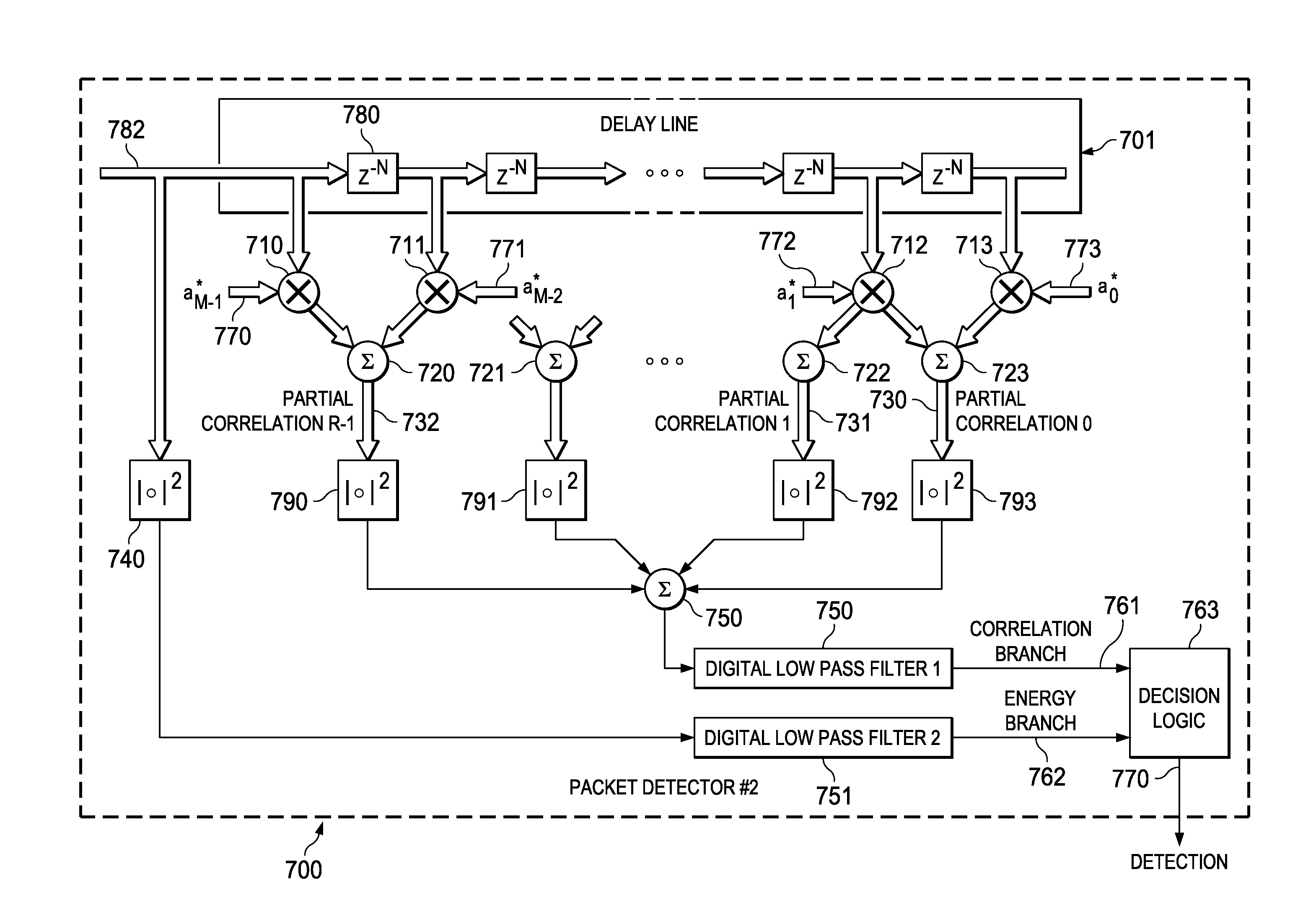
[0073]In operation, the input signal sample stream is delayed using delay line 701. Please note that in this second embodiment, the delay line atomic delay comprises N samples, where N is equal to the signal period. The delayed version of the signal samples are then multiplied by the flipped version of the spread sequence aM−1*, aM−2*, . . . a1*, a0* 1770, 1771, 1772, 1773, respectively. R partial correlation signals are then generated via summers 720, 721, 722, 723. Each partial correlation value undergoes a square magnitude operation via blocks 790, 791, 792, 793. The output of these square magnitude blocks are then summed together using summer 750. The signal then undergoes digital low pass filtering via block 750 in order to smooth out signal transients and noise effects. The output of the filtering stage is the correlation branch signal 761.

[0074]An energy branch signal 762 is generated by taking the input signal samples 782 and passing them through a square magnitude operation...

third embodiment

[0082]A block diagram illustrating a carrier frequency offset estimation circuit using the packet detection mechanism of the present invention is shown in FIG. 10. The packet detector, generally referenced 900, comprises delay line 901 comprising a plurality of delay elements 980, a first plurality of multipliers 902, 903, 904, 905, a plurality of summers 920, 921, 922, 923, a second plurality of multipliers 930, 931, 932, summer 950, digital low pass filter #1951 and angle detector 952.

[0083]In operation, the input signal sample stream 982 undergoes a delay line 901, whose atomic delay is the reference signal period N. The delayed signal samples are multiplied using a plurality of multipliers 902, 903, 904, 905 with the conjugated flipped version of the delayed signal aM−1*, aM−2*, . . . a1*, a0* 910, 911, 912, 913, respectively. Various combinations of the delayed signal samples multiplied by the reference signal samples are summed together via summers 920, 921, 922, 923. Pairs of...


PUM


Abstract

A novel and useful apparatus for and method of packet detection and carrier frequency offset estimation. The packet detection mechanism is robust to channels and sustains reasonable miss-detect (and false alarm) rates at low SNR values. The mechanism uses a modified combined cross correlation and delay and correlate scheme. A delay and correlate scheme is used in order to handle the effects of multipath while swapping integration and multiplication to increase cross-correlation factors resulting in improved sensitivity in low SNR conditions. Correlation is divided into multiple chains to generate a plurality of partial correlations to observe short patterns in the spread sequence resulting in improved performance in long multipath channels.

Description

REFERENCE TO PRIORITY APPLICATION[0001]This application claims priority to U.S. Provisional Application Ser. No. 60 / 745,589, filed Apr. 25, 2006, entitled “UWB Packet Detection and Coarse Frequency Carrier Offset Estimation Design Review”, incorporated herein by reference in its entirety.FIELD OF THE INVENTION[0002]The present invention relates to the field of data communications and more particularly relates to an apparatus for and method of robust packet detection and frequency offset estimation for use in a digital receiver.BACKGROUND OF THE INVENTION[0003]The use of packet data transmission and reception is well known in the art. Digital data in the form of a bit stream is assembled into packets, modulated using a modulation scheme and transmitted over a medium (i.e. channel). At the other end of the communications channel, a receiver tries to receive the packet and demodulate the signal back into the original bit stream.[0004]A high level block diagram of a prior art wireless r...

Claims


Application Information

Patent Timeline
Patent Type & Authority Patents(United States)
IPC IPC(8): H04L27/00H04L27/26H04L7/04H04L7/08
CPCH04L27/2656H04L7/042H04L27/2657H04L27/2679H04L7/08H04L2027/0046H04L2027/0065
Inventor LERNER, GREGORYTAL, NIRWOLBERG, DANSINGH, MANONEETAZENKOT, YEHUDA
Owner TEXAS INSTR INC
Why Eureka
Try Eureka