Animated light string system

a string system and light technology, applied in the field of strings of lights, can solve the problems of limiting the types of displays available, requiring a substantial amount of wiring,

Inactive Publication Date: 2013-02-19
PETERSON JOHN W
View PDF14 Cites 32 Cited by
  • Summary
  • Abstract
  • Description
  • Claims
  • Application Information

AI Technical Summary

Problems solved by technology

(2007) requires a substantial amount of wiring, which becomes cumbersome with significant numbers of lights.
U.S. Pat. Nos. 7,471,048 (2008) and 7,576,497 (2009) due to Peng, provide a method of synchronizing the lights, but no straightforward way to individually program them, thus limiting the types of displays available.

Method used


Image

  • Animated light string system
  • Animated light string system
  • Animated light string system

Examples


Embodiment Construction

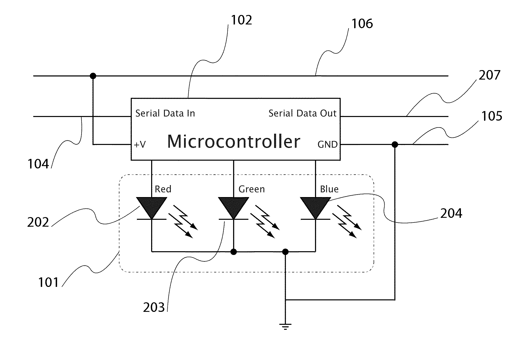
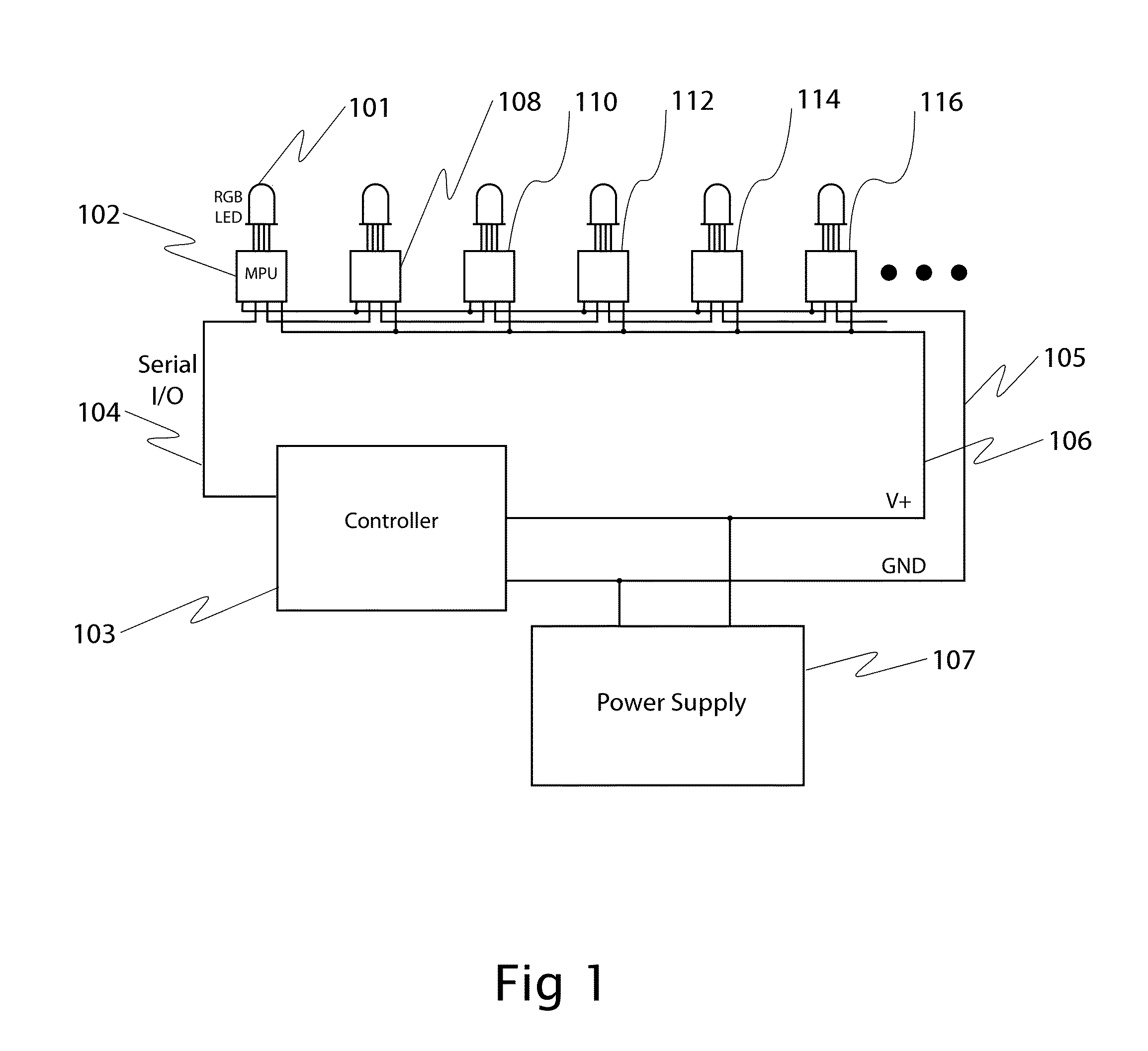
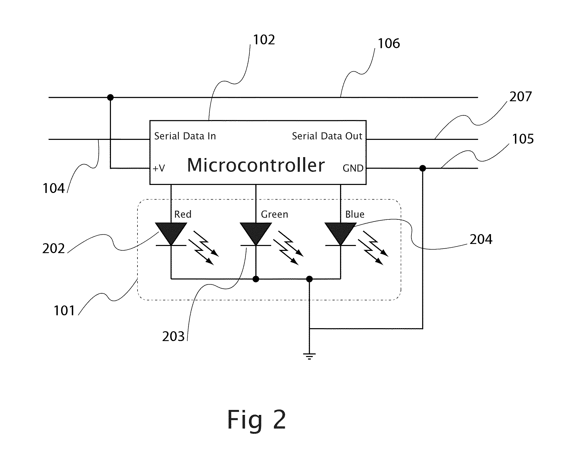
[0033]A schematic drawing of a first embodiment of the invention is shown in FIG. 1. Each RGB Light Emitting Diode 101 has three component LEDs, red green and blue. These LEDs share a common cathode and have separate inputs for powering the red, green and blue component LED anodes. A microcontroller 102 is connected to each RGB LED anode. By controlling the duty cycle using pulse-width modulation (PWM), the brightness of each component LED is controlled, thus controlling the overall brightness and color.

[0034]In addition to controlling the LED, each microcontroller also listens to a serial control line 104. The serial control lines of each of the lights are connected in a “daisy chain” fashion, where the output of a light's microcontroller is connected to the input of a subsequent light's microcontroller. An external controller 103, such as another microcontroller, personal computer, or network serial interface is connected to the serial input of the first microcontroller in the str...


PUM


Abstract

A system for controlling a string of lights, where each light or group of lights has a microcontroller for controlling their brightness and color. The light's microcontrollers are connected with serial data communication lines in a daisy chain fashion. Unique identification numbers are automatically assigned sequentially to each of the lights so brightness or color information transmitted on the serial data line is directed to a particular light. A plurality of brightness and color settings are stored on each light, and the string of lights synchronously switches between them on command from the serial line, or smoothly fades between them on command from the serial line.

Description

CROSS-REFERENCE TO RELATED APPLICATIONS[0001]This application claims the benefit of the U.S. Provisional Patent Application having Application No. 61 / 214,029 and filed on Apr. 17, 2009, the disclosure of which is incorporated by reference herein.PROGRAM LISTINGS[0002]Computer Program Listing 1 (LEDctlr.c) is a C program suitable for execution on a microcontroller for implementing the invention.[0003]Computer Program Listing 2 (ControllerDemonstration.py) is a Python program to run on an external computer to display patterns on the lights.BACKGROUND[0004]1. Field of the Invention[0005]This invention relates to strings of lights used for the purpose of decoration, signage, or architectural accents, with lights that change color and brightness.[0006]2. Prior Art[0007]The following is a tabulation of some prior art that presently appears relevant:[0008]Patent / Pub. #Kind CodeIssue DateInventor2005 / 0269580A12005D'Angelo6,608,453B22003Morgan, et al.7,257,551B22007Oskorep et al.7,550,935B22...

Claims


Application Information

Patent Timeline
Patent Type & Authority Patents(United States)
IPC IPC(8): G05B23/02
CPCH05B33/0842H05B37/0254H05B37/029H05B45/325H05B47/155H05B47/18
Inventor PETERSON, JOHN W.
Owner PETERSON JOHN W
Why Eureka
Try Eureka