
Heat management and reduction of high temperatures exposure to components inside energy meter

a technology of energy meters and components, applied in indirect heat exchangers, lighting and heating devices, instruments, etc., can solve the problems of excessive temperature rise inside the cover of the meters, and the amount and/or functionality of electronic circuitry within the meters may be limited

Inactive Publication Date: 2013-02-19
GENERAL ELECTRIC CO
View PDF45 Cites 4 Cited by
  • Summary
  • Abstract
  • Description
  • Claims
  • Application Information

AI Technical Summary

Benefits of technology

The invention relates to a way to keep an electric meter housing with heat-generating components cool. The method involves using an outer sealed enclosure with air channels between it and the outside. The air circulates around the components and removes enough heat to keep them safe and operating properly.

Problems solved by technology

A problem sometimes encountered with utility meters that employ electronic circuits is excessive temperature rise inside the cover of the meter due to heat generated by electronic components and by other electrical components within the meter.
Unfortunately, electric meters must be enclosed in such a manner as to pass the metering industry's weatherization standards, which require meter enclosures to be sealed from dust and water.
As a consequence, the amount and / or functionality of electronic circuitry within meters may be limited at least partly by the associated heat rise caused by additional circuitry and / or functionality.

Method used


Image

  • Heat management and reduction of high temperatures exposure to components inside energy meter
  • Heat management and reduction of high temperatures exposure to components inside energy meter
  • Heat management and reduction of high temperatures exposure to components inside energy meter

Examples


Embodiment Construction

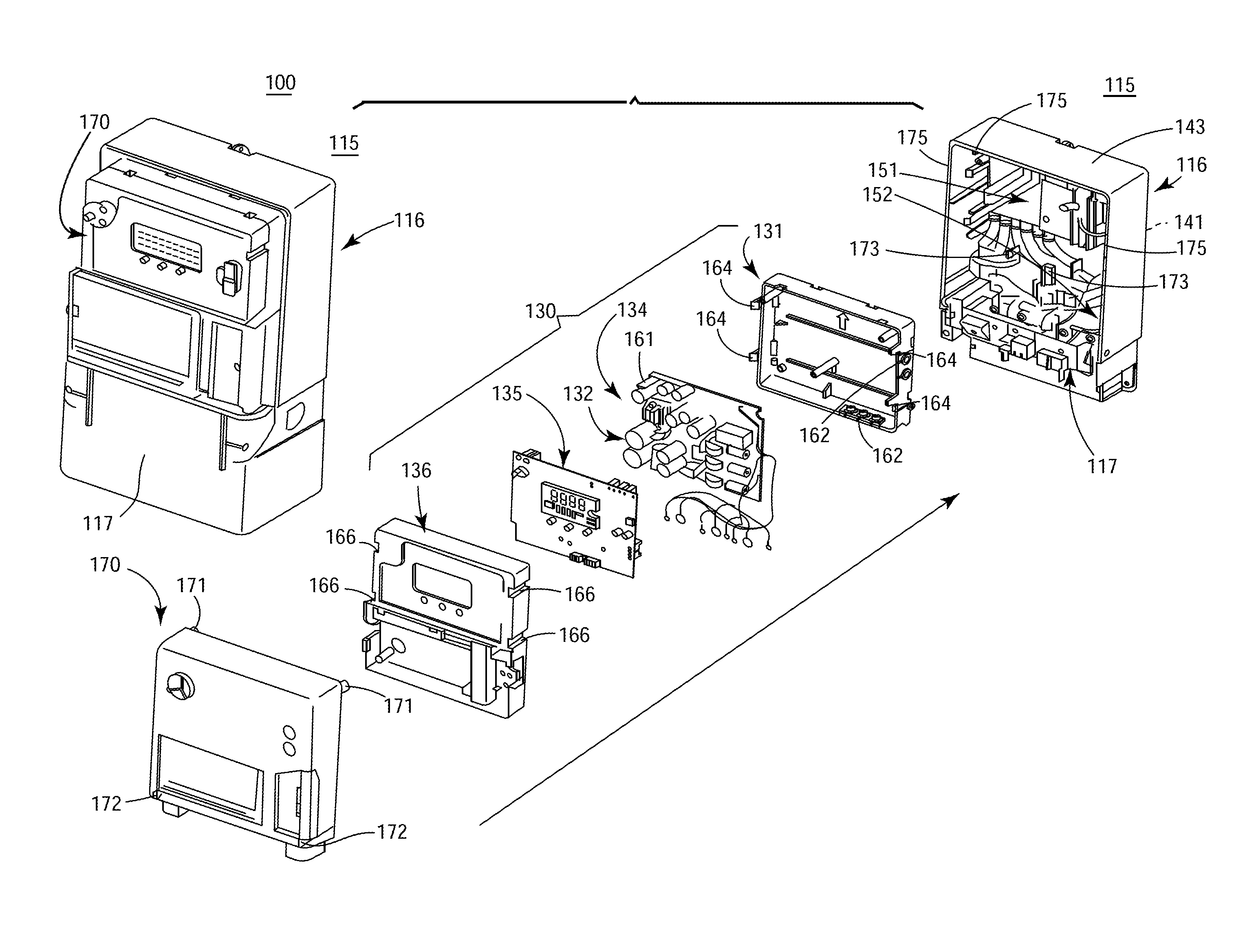
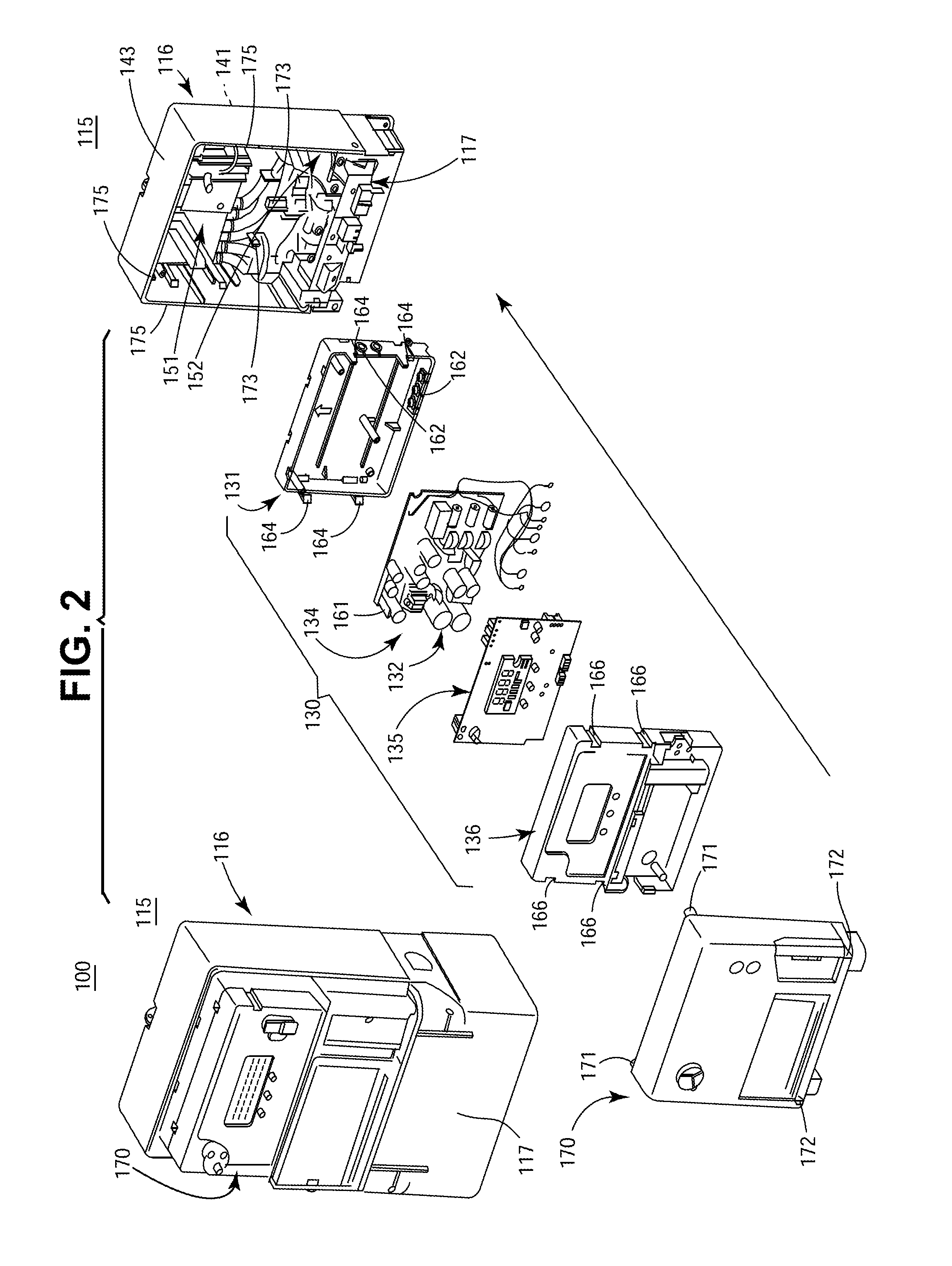
[0012]The following embodiments of the present invention have many advantages, including mounting encapsulated of electronic components of the utility meter within a sealed outer enclosure with air channels between the encapsulated electronic components and the sealed outer enclosure to deliver sufficient thermal air circulation there-between promoting sufficient heat transfer through an outer skin of the sealed outer enclosure for maintaining acceptable thermal conditions for the encapsulated electronic components.

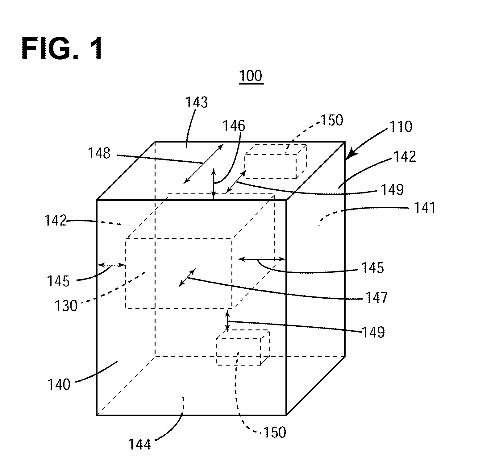
[0013]FIG. 1 illustrates a simplified view of an inventive energy meter 100 that includes an outer sealed enclosure 110, an encapsulated compartment 130 for housing electronic components (not shown), and a plurality of high heat generating components 150. The outer sealed enclosure 110 includes a front wall 140, a back wall 141, sidewalls 142, a top surface wall 143 and a bottom surface wall 144. The encapsulated compartment 130 housing the electronics is mounted within t...


PUM


Abstract

Electronic components of an energy meter are mounted in an encapsulated compartment within a sealed outer enclosure of the meter. The encapsulated compartment is advantageously positioned to form air channels between the encapsulated compartment and the sealed outer enclosure to deliver thermal air circulation there-between to promote sufficient heat transfer through an outer skin of the sealed outer enclosure for maintaining acceptable thermal conditions for the encapsulated electronic components.

Description

BACKGROUND OF THE INVENTION[0001]The invention relates generally to electric metering devices and more specifically to heat management for electronics within such devices.[0002]Traditional utility meters for the measurement of electricity primarily employed mechanical registers and devices. While electricity meters always contained devices that sense electrical energy, the registration of such sensed energy was often carried out mechanically using gears and dials. More recently, utility meters have increasingly relied upon electronic circuits that provide enhanced functionality. At present, electricity meters often contain one or more circuit boards that provide advanced consumption registration functions, automatic meter reading functions, diagnostics, profiling and other beneficial functions.[0003]A problem sometimes encountered with utility meters that employ electronic circuits is excessive temperature rise inside the cover of the meter due to heat generated by electronic compon...

Claims


Application Information

Patent Timeline
Patent Type & Authority Patents(United States)
IPC IPC(8): H05K7/20F28D15/00
CPCG01R22/06H05K7/202G01R1/44
Inventor NEHETE, CHANDRASHEKHAR SADASHIVNEMADE, SANDEEP YOGRAJ
Owner GENERAL ELECTRIC CO
Learn More