Disc device

a disc device and cam groove technology, applied in the field of disc devices, can solve the problems of reducing the degree of flexibility in the design of the disc device, becoming very narrow, etc., and achieve the effect of stabilizing the operation of the disc device and reducing the friction force applied to the cam groov

Inactive Publication Date: 2013-02-26
MITSUBISHI ELECTRIC CORP
View PDF20 Cites 2 Cited by
  • Summary
  • Abstract
  • Description
  • Claims
  • Application Information

AI Technical Summary

Benefits of technology

[0004]In the conventional disc device constructed as mentioned above, because the spring load is proportional to the frictional force added to the cam groove, an upper limit of the spring load for ensuring the rotational driving force of the cam gear needs to be set, and a lower limit of the spring load required to make the elastic member exert its spring effect also needs to be set. A problem is therefore that when environmental conditions, such as temperature, are also taken into consideration, the range of the spring load which can guarantee the disc device to operate as usual becomes very narrow, and the degree of flexibility in the design of the disc device is reduced.
[0005]The present invention is made in order to solve the above-mentioned problem, and it is therefore an object of the present invention to provide a disc device that carries out operations with stability while reducing a frictional force applied to a cam groove, thereby reducing a rotational load imposed on a cam gear.
[0007]Because the disc device in accordance with the present invention is constructed in such a way as to include the protruding portion disposed on the operation member, the protruding portion being brought into contact with the end portion of the rotary lever at the initial position of the above-mentioned operation member before the operation member starts operating, so as to restrict the rotation of the above-mentioned rotary lever in such a way that the pin does not come into contact with the wall surface of the cam groove, a frictional force applied to the cam groove can be reduced without impairing the function of the cam groove, and therefore a rotational load imposed on the cam gear can be reduced. As a result, the operation of the disc device can be stabilized.

Problems solved by technology

A problem is therefore that when environmental conditions, such as temperature, are also taken into consideration, the range of the spring load which can guarantee the disc device to operate as usual becomes very narrow, and the degree of flexibility in the design of the disc device is reduced.

Method used


Image

  • Disc device
  • Disc device
  • Disc device

Examples


embodiment 1

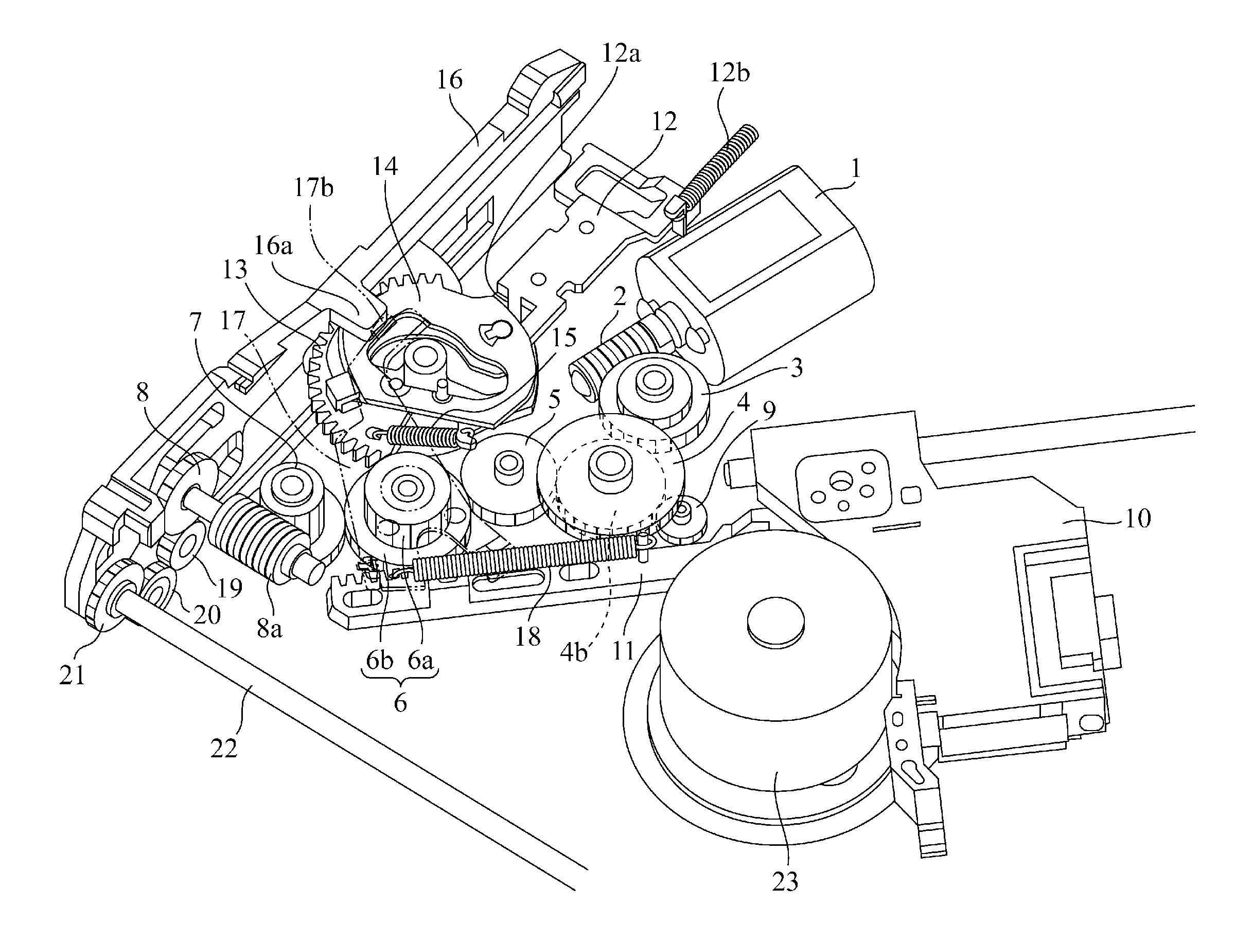
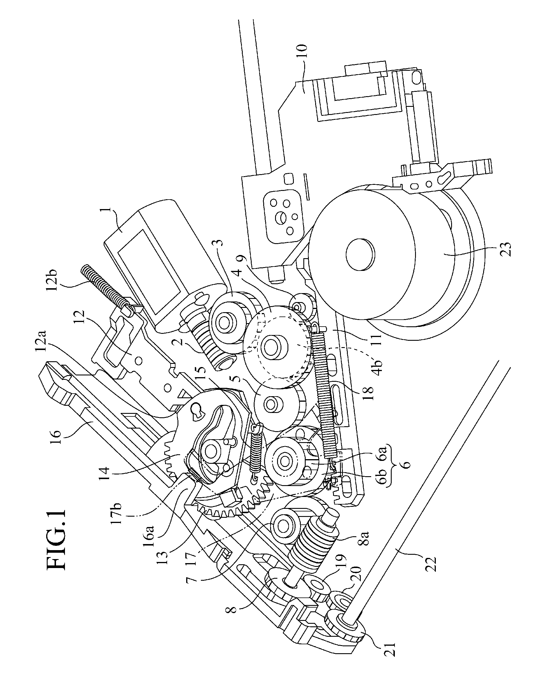
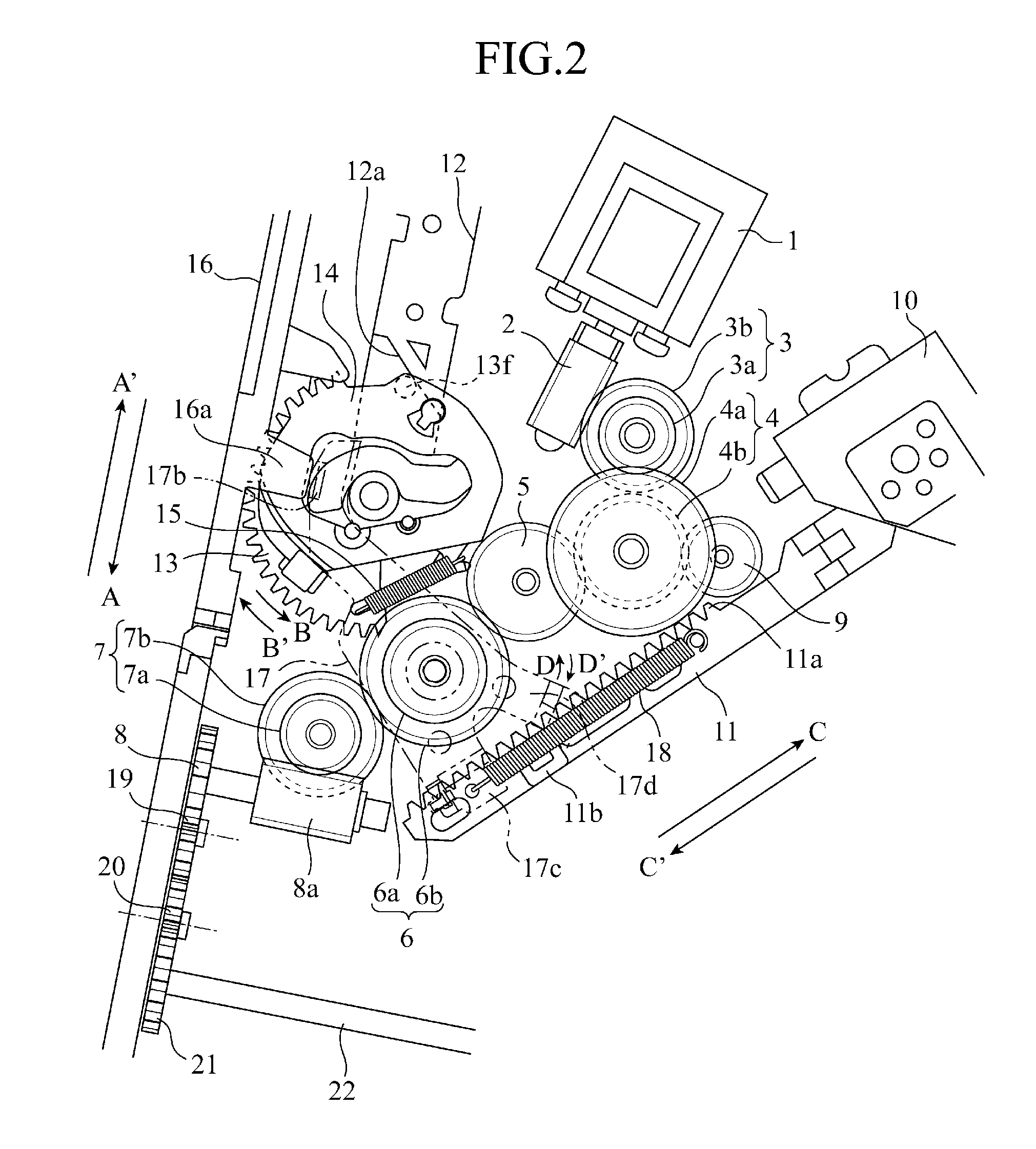
[0015]FIG. 1 is a perspective view showing a power switching unit of a disc device in accordance with Embodiment 1, and FIG. 2 is a plane view of the power switching unit. This disc device will be explained hereafter, focusing on disc conveying which is an initial state, mode switching at the time of making a transition from the disc conveying state to a pickup feeding state, and transmitting power in the pickup feeding.

[0016]This disc device is provided with main components including a motor 1 which is a driving source, a worm gear 2 attached to the rotatable shaft of the motor 1, a plurality of gears 3 to 9 and 19 to 21 for propagating the rotation of the worm gear 2, a pickup 10 for performing a process of reading an information signal on a disc, a rack gear (a first rack gear) 11 disposed to extend in a movement direction of the pickup 10, a trigger member 12 that operates when detecting an insertion of a disc into the disc device to perform an operation of making a transition t...


PUM

PropertyMeasurementUnit
movementaaaaaaaaaa
timeaaaaaaaaaa
rotational forceaaaaaaaaaa

Abstract

A disc device has a sliding member 16 that operates in response to a rotational force of the first partially toothless gear 13 to disconnect a power transmission system from a disc conveying roller, and a protruding portion 16a disposed on this sliding member 16 is brought into contact with a rising portion 17b of a rotary lever 17 at an initial position of the sliding member before the sliding member starts operating, so as to restrict a rotation of the rotary lever 17 in such a way that a pin 17a does not come into contact with a wall surface of a cam groove 13d.

Description

FIELD OF THE INVENTION[0001]The present invention relates to a disc device that carries out disc conveying and pickup feeding by using a single power source.BACKGROUND OF THE INVENTION[0002]This type of disc device has a mechanism of rotating a rotary lever by using a cam gear, and a fixed spring load is always imposed on this rotary lever by an elastic member. A sliding pin which comes into contact with a cam groove of the cam gear is formed in the rotary lever, and, when the spring load is imposed on the rotary lever, this spring load serves as a frictional force added to the cam groove via the sliding pin. As a result, the frictional force becomes a rotational load imposed on the cam gear. Patent reference 1 discloses a technology of, in order to control this rotational load, adjusting the shape of the wall surface of the cam groove to adjust the amount of expansion and contraction of the elastic member, thereby adjusting the frictional force added to the cam groove.RELATED ART D...

Claims


Application Information

Patent Timeline
Patent Type & Authority Patents(United States)
IPC IPC(8): F16H21/16G11B17/04G11B7/00
CPCG11B17/04G11B17/05G11B17/0404Y10T74/1828
Inventor ONISHI, AKIHITOEGUCHI, TAKAHARUAWAKURA, YOSHIFUMIFUJIWARA, TATSUNORITSUKAGUCHI, AKINORI
Owner MITSUBISHI ELECTRIC CORP
Why Eureka
Try Eureka