Fishbone well configuration for in situ combustion

a technology of in situ combustion and fishbone wells, which is applied in the direction of fluid removal, borehole/well accessories, survey, etc., can solve the problems of suffocation of the combustion front and lack of oil mobility

Active Publication Date: 2013-02-26
CONOCOPHILLIPS CO
View PDF17 Cites 10 Cited by
  • Summary
  • Abstract
  • Description
  • Claims
  • Application Information

AI Technical Summary

Problems solved by technology

One difficulty associated with applying in situ combustion as a stand alone recovery method in heavy oil and bitumen reservoirs is the lack of mobility of the oil.
Therefore, combustion gas products (CO, CO2, H2S, etc.) and mobilized oil can become trapped in the reservoir which leads to the suffocation of the combustion front.

Method used


Image

  • Fishbone well configuration for in situ combustion
  • Fishbone well configuration for in situ combustion

Examples


Embodiment Construction

[0010]Reference will now be made in detail to embodiments of the present invention, one or more examples of which are illustrated in the accompanying drawing. Each example is provided by way of explanation of the invention, not as a limitation of the invention. It will be apparent to those skilled in the art that various modifications and variations can be made in the present invention without departing from the scope or spirit of the invention. For instance, features illustrated or described as part of one embodiment can be used on another embodiment to yield a still further embodiment. Thus, it is intended that the present invention cover such modifications and variations that come within the scope of the appended claims and their equivalents.

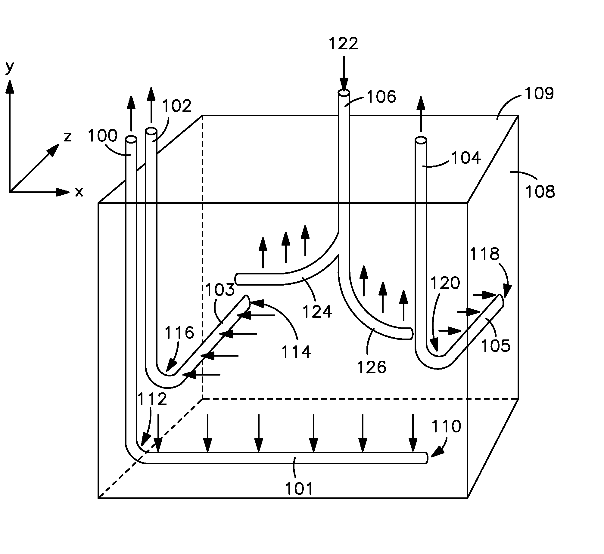
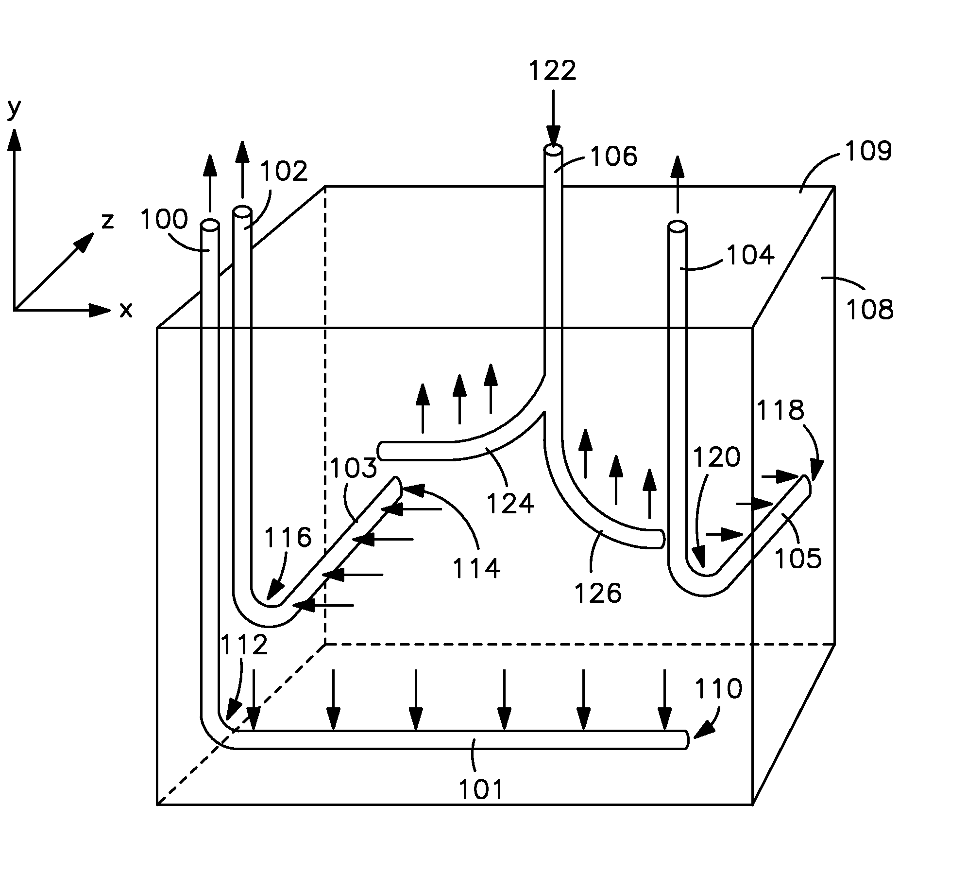
[0011]Referring to FIG. 1, an underground reservoir 108 contains an injection well 106 and a series of production wells 100, 102, 104 disposed therein. The “x-axis” is parallel to the earth surface 109. The “y-axis” is orthogonal to the x-axi...


PUM


Abstract

An underground reservoir is provided comprising an injection well and a production well. The production well has a horizontal section oriented generally perpendicularly to a generally linear and laterally extending, upright combustion front propagated from the injection well.

Description

CROSS-REFERENCE TO RELATED APPLICATIONS[0001]This application claims priority benefit under 35 U.S.C. Section 119(e) to U.S. Provisional Patent Ser. No. 61 / 245,321 filed on Sep. 24, 2009 the entire disclosure of which is incorporated herein by reference.FIELD OF THE INVENTION[0002]Embodiments of the invention relate to a method for recovering hydrocarbons with in situ combustion.BACKGROUND OF THE INVENTION[0003]In situ combustion (ISC) processes are applied for the purpose of recovering oil from light oil, medium oil, heavy oil and bitumen reservoirs. In the process, oil is heated and displaced to an open production well for recovery. Historically, in situ combustion involves providing spaced apart vertical injection and production wells within a reservoir. Typically, an injection well will be located within a pattern of surrounding production wells. An oxidant, such as air, oxygen enriched air or oxygen, is injected through an injection well into a hydrocarbon formation, allowing c...

Claims


Application Information

Patent Timeline
Patent Type & Authority Patents(United States)
IPC IPC(8): E21B43/243
CPCE21B43/243
Inventor DREHER, JR., WAYNE R.SARATHI, PARTHA S.
Owner CONOCOPHILLIPS CO
Why Eureka
Try Eureka