Modified process for hydrocarbon recovery using in situ combustion

a technology of in situ combustion and hydrocarbon recovery, which is applied in the direction of drinking water installation, borehole/well accessories, construction, etc., can solve the problems of increasing environmental footprint, increasing cost, and impact of drilling operations on the environment, so as to reduce the cost of in situ recovery and reduce the number of steps

Inactive Publication Date: 2010-11-30
ARCHON TECH LTD
View PDF13 Cites 1 Cited by
  • Summary
  • Abstract
  • Description
  • Claims
  • Application Information

AI Technical Summary

Benefits of technology

[0007]The method of the present invention is to a modified in situ hyrdrocarbon recovery process that instead of injecting oxidizing gas near the “toe” portion of the horizontal leg injects oxidizing gas in or near the producing vertical section of the producing well (ie at the “heel” portion). The modified process obviates the need for a separate drilling / production pad for oxidizing gas injection, thereby reducing cost and decreasing detrimental environmental impact of in situ recovery methods.
[0008]Advantageously, the process of the present invention in a particular third embodiment described below further eliminates the need for a separate oxidizing gas injection well, in that in such refinement the vertical section of the production well also serves as the injection well, thereby reducing well drilling costs and reducing the capital costs.

Problems solved by technology

Disadvantageously, in each of the above prior art methods for recovering liquefied and / or gasified hydrocarbons from a hydrocarbon formation oxidizing gas is needed to be injected proximate the toe of the horizontal leg, and remote from the vertical section of the production well.
Such requires clear access, via clearcutting, and / or increased space at the injection well site to accommodate additional oxidizing gas delivery and / or generation and compression facilities, thereby increasing the environmental “footprint” and impact of drilling operations on the environment, and also typically results in increased cost.

Method used


Image

  • Modified process for hydrocarbon recovery using in situ combustion
  • Modified process for hydrocarbon recovery using in situ combustion
  • Modified process for hydrocarbon recovery using in situ combustion

Examples


first embodiment

[0066]The method of the present invention, in the first embodiment shown in FIGS. 2A-2C, thereafter operates as follows:

[0067]Oxidizing gas 24 is injected into formation 10 via injection well 22. Advantageously, equipment (not shown) used to create oxidizing gas 24 and inject such oxidizing gas 24 need not be located remote from the production well 12, but instead can, by virtue of the method of the present invention, be located proximate to production well 12, and in particular if desired may be located on drilling pad 32 or closely proximate thereto, thereby eliminating the need for clearing and creating a separate drilling pad at a remote site such as would occur if the injection well 22 were located towards the “toe” of horizontal well 16. Also, operation and maintenance of the oxidizing gas supply equipment can conveniently be conducted at the oil-treating site located near well 12. Hydrocarbons proximate the injection well 22 are ignited, and due to the supply of oxidizing gas...

third embodiment

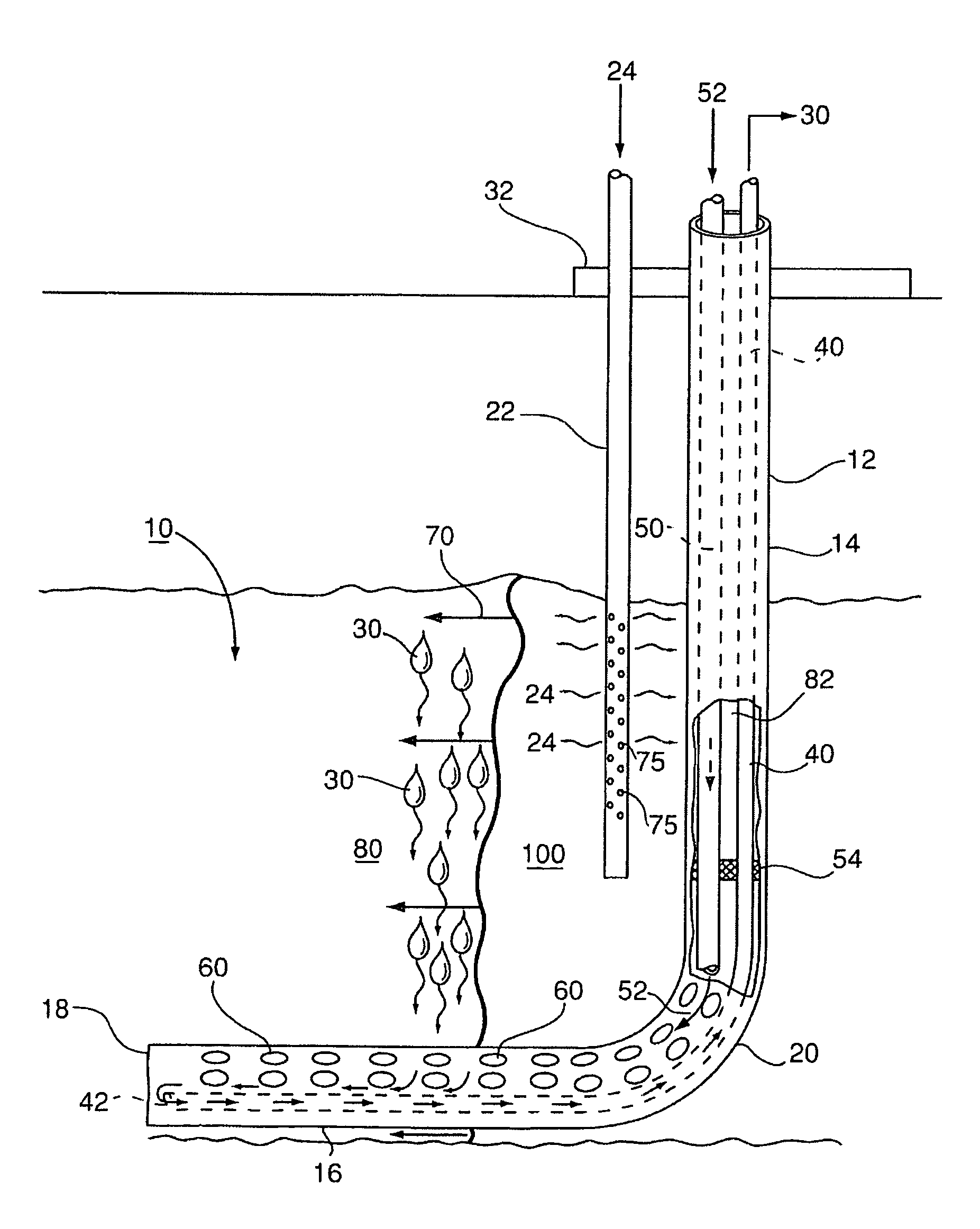
[0079]Importantly, however, in this third embodiment of the method of the present invention shown in FIG. 4, there is no step of drilling an injection well 22. Instead, perforations 110 are made in the vertical section 16 of production well 12, and an oxidizing gas 24 injected into such vertical section 16 and thus into formation 10. Oxidizing gas 24 is prevented from injection into horizontal leg 16 by the presence of isolation packers 54 which effectively separate produced liquefied hydrocarbons in horizontal leg 16 from oxidizing gas 24 such as oxygen, thereby preventing formation of explosive mixtures. Injection tubing 50 still serves, like in earlier embodiments, to permit sporadic or continuous injection of non-oxidizing gas 52 into horizontal leg 16 to prevent oxidizing gas 24 within the burned zone 80 of the formation from permeating into horizontal leg 16.

[0080]Advantageously, using the method depicted in FIG. 4, the cost of drilling an injection well 22 is completely elimi...


PUM


Abstract

A modified method for in situ recovery of hydrocarbon from an underground hydrocarbon-containing formation. An “L” shaped production well, having a vertical section, and a lower horizontal leg positioned low in the formation, is provided. The horizontal leg connects to the vertical section at a heel portion, and has a toe portion at an opposite end thereof. Oxidizing gas is injected into the formation in or proximate the vertical section. A combustion front sweeps outwardly from the vertical section and laterally within the formation above the horizontal leg, from the heel to the toe, causing hydrocarbons in the formation above the horizontal leg to drain downwardly into the horizontal leg, which are then delivered to surface via production tubing. A non-oxidizing gas is injected into at least the heel portion and preferably additional portions of the horizontal leg via injection tubing contained within the vertical section of the production well.

Description

FIELD OF THE INVENTION[0001]This invention relates to an modified process for hydrocarbon recovery from an underground reservoir by in situ combustion and employing a horizontal production well.BACKGROUND OF THE INVENTION[0002]Commonly assigned U.S. Pat. No. 5,626,191 issued May 6, 1997 (hereinafter the '191 patent) discloses an in situ combustion processes for producing hydrocarbon from an underground hydrocarbon reservoir utilizing (i) at least one injection well placed relatively high in an oil reservoir for injecting an oxidizing gas into the hydrocarbon formation, and (ii) a production well for producing liquefied or gasified hydrocarbon from the hydrocarbon reservoir. The production well has a vertical section which is in communication with a horizontal leg extending substantially perpendicularly outwardly from the vertical section and having a “toe” portion and a “heel” portion. The horizontal leg is completed relatively low in the reservoir, and at a “heel” portion thereof i...

Claims


Application Information

Patent Timeline
Patent Type & Authority Patents(United States)
IPC IPC(8): E21B43/243
CPCE21B43/243E21B43/305
Inventor AYASSE, CONRADWU, XINJIEBLOOMER, CHRIS
Owner ARCHON TECH LTD
Why Eureka
Try Eureka