Rakelet

a technology of wingtips and rakelets, applied in the direction of airflow influencers, influencers by generating vortices, aircraft stabilisation, etc., to achieve the effect of improving lift, reducing drag and wingtip vortex strength, and improving endurance and rang

Inactive Publication Date: 2013-02-26
AIR FORCE US SEC THE THE
View PDF15 Cites 31 Cited by
  • Summary
  • Abstract
  • Description
  • Claims
  • Application Information

AI Technical Summary

Benefits of technology

[0007]Rakelets improve endurance and range over standard aircraft wings and over other wingtip devices such as raked wingtips and winglets. They integrate features of raked wingtips and winglets into a wingtip device that exploits the advantages of raked wingtips or winglets over each wingtip device employed separately. Rakelets reduce induced drag and wingtip vortex strength and improve lift over standard wings and other wingtip devices. They can be configured to maximize endurance and range for an aircraft thereby improving fuel efficiency and performance over the baseline performance of the aircraft, and also over range and endurance improvements provided by other wingtip devices such as raked wingtips and winglets.
[0008]A rakelet wingtip device for an aircraft comprises a raked portion having an airfoil-shaped cross section, a proximal end, a distal end forming a wingtip chord, an upper surface, a lower surface, a leading edge, and a trailing edge, wherein the proximal end can be attached to a distal end of an aircraft wing and the leading edge and/or the trailing edge has a sweep angle greater than a sweep angle of a corresponding leading or trailing edge of the aircraft wing; and a winglet portion having an airfoil-shaped cross section, a proximal end, a distal end, an upper surface, a lower surface, a cant angle, and a toe angle, wherein the proximal end is attached to the wingti

Problems solved by technology

This phenomenon causes high speed, low pressure regions of rotational flow around the wingtip that drains energy from the aircraft in the for

Method used


Image

  • Rakelet
  • Rakelet
  • Rakelet

Examples


Embodiment Construction

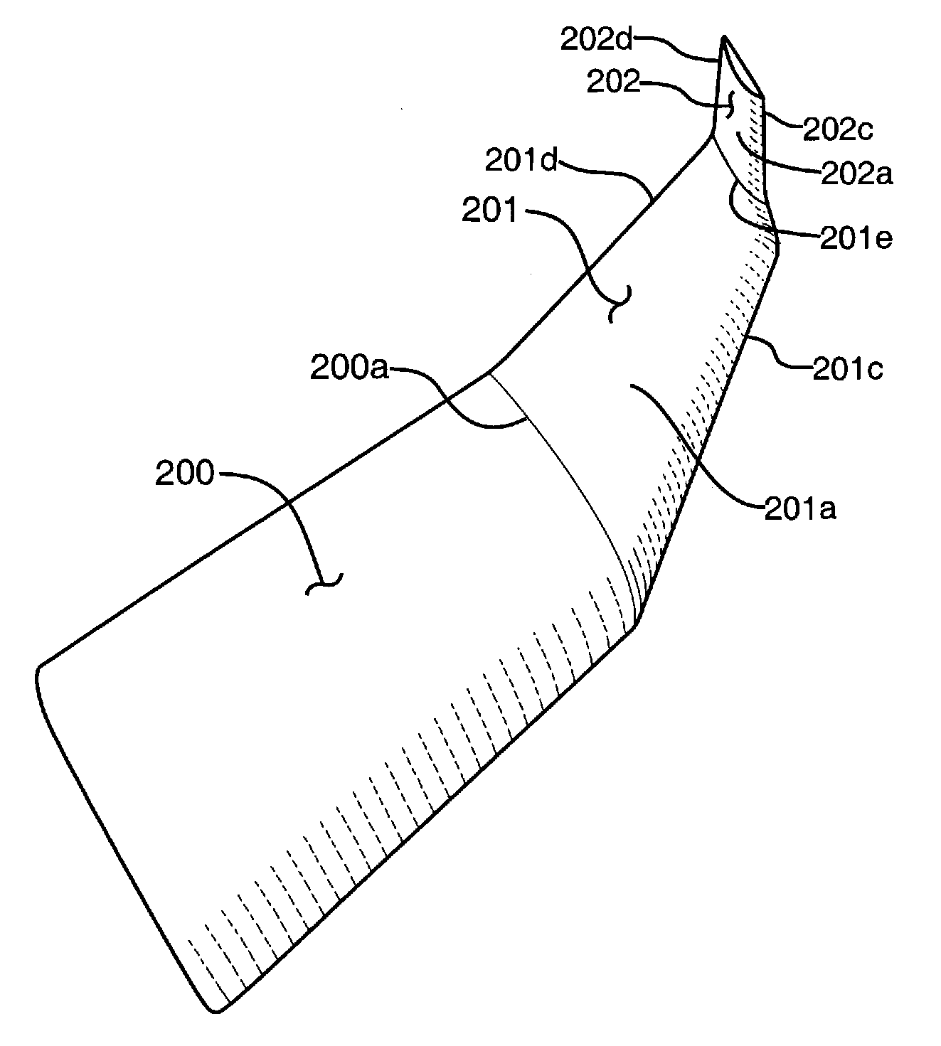
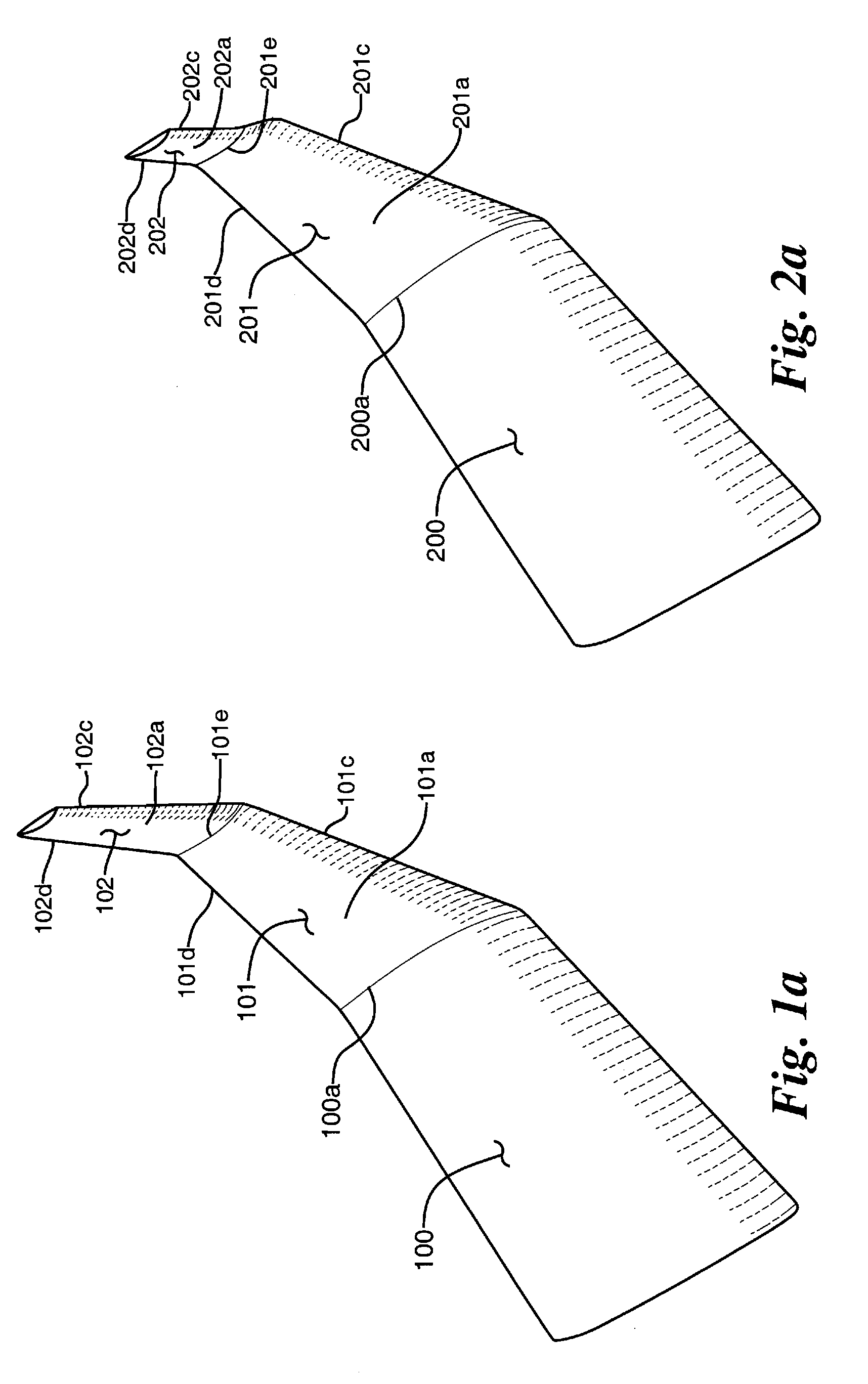
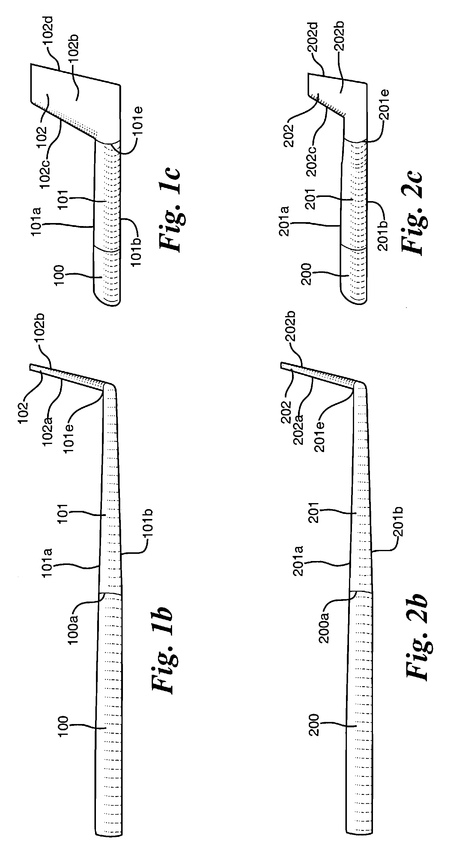
[0035]As shown in FIGS. 1 and 2, a rakelet is positioned on a distal portion of an aircraft wing 100, 200. The rakelet comprises a raked portion 101, 201 and a winglet portion 102, 202. The raked portion 101, 201 has an airfoil-shaped cross section that generates lift across it. The raked portion 101, 201 comprises a curved upper surface 101a, 201a, a generally planar lower surface 101b, 201b, a leading edge 101c, 201c, and a trailing edge 101d, 201d. The raked portion 101, 201 can be connected along the wingtip chord 100a, 200a of a standard aircraft wing 100, 200. The leading edge 101c, 201c and / or the trailing edge 101d, 201d of the raked portion 101, 201 may have a sweep angle greater than the sweep of the wing 100, 200 to which the rakelet is attached, as shown in FIGS. 1a and 2a.

[0036]The winglet portion 102, 202 has an airfoil-shaped cross-section that generates lift across it. The winglet portion 102, 202 comprises a curved upper surface 102a, 202a and a generally planar lo...


PUM


Abstract

A rakelet comprises a raked portion and a winglet portion that selectively integrate features of raked wingtips and winglets into a wingtip device that improves aircraft endurance and range over standard wings and over other wingtip devices such as raked wings, winglets, and the like. The features of the rakelet can be configured to improve and maximize the range and endurance for any particular aircraft.

Description

RIGHTS OF THE GOVERNMENT[0001]The invention described herein may be manufactured and used by or for the Government of the United States for all governmental purposes without the payment of any royalty.TECHNICAL FIELD[0002]This application discloses aircraft wingtips that improve endurance, range, and performance over standard aircraft wings and other wingtip devices.BACKGROUND[0003]Wingtip devices modify the airflow around an aircraft's wingtip to improve the aerodynamic efficiency of the wing. Wingtip devices can improve the aerodynamic capabilities of an aircraft by reducing the effect of wingtip vortices. Wingtip vortices are created when high pressure air below the wing migrates around the wingtip to the low pressure regions above the wing. This phenomenon causes high speed, low pressure regions of rotational flow around the wingtip that drains energy from the aircraft in the form of induced drag. Conventional wingtips produce strong vortices that can account for more than half ...

Claims


Application Information

Patent Timeline
IPC IPC(8): B64C23/00
CPCB64C23/065Y02T50/164B33Y80/00B64C23/069Y02T50/10
Inventor YECHOUT, THOMAS R.
Owner AIR FORCE US SEC THE THE
Why Eureka
Try Eureka